38
SECTION 4
Parallel Connection Methods
F210
Setup Manual
SECTION 4
Connecting External Devices
Parallel Connection Methods
The Controller’s parallel interface (RS-232C/RS-422 connector or Ethernet connector) can be used to
input signals such as measurement triggers or output signals such as measurement results.The
connection method is explained here.
The interface can be connected in two ways: via “I/O terminal” and via “I/O connector”. Connect it by one
of the two ways. It is not possible to use both.
If the I/O signals include necessary control signals, wire the signals to the connector (MC1.5/10-STF-3.5
by Phoenix Contact, supplied with the controller) and connect it to the controller. If you want to input
commands and output measurement results via the parallel interface, have a parallel I/O cable (optional)
ready and connect it to the I/O connector.
For the communication parameter setting method and I/O format, refer to the Operation Manual.
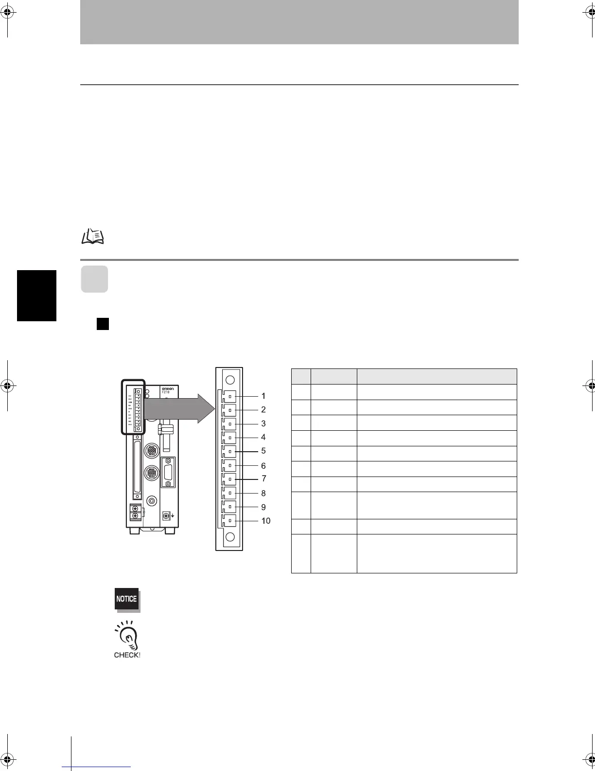
I/O Terminals
Wiring method
Wire the cable to the connector (supplied with the controller) and plug it into the controller.
Terminal assignment on the controller side is shown below.Wire only necessary terminals.
Do not input the RESET input immediately after turning ON the power.When using the RESET input to synchronize
startup timing, wait at least 1 second after the Controller’s power supply is turned ON before turning ON the
RESET signal.
Use a DC power supply with countermeasures against high voltages (safe extra low-voltage circuits on the
secondary side) for the COMIN and COMOUT terminals.If the system must meet UL standards, use a UL class II
power supply.
Pin Signal Function
1STEP
Measurement trigger signal (input terminal)
2 RESET
Controller restart (input terminal)
3COMIN
Common for input signals
4RUN
ON while in Run mode (output terminal)
5ERROR
ON when there is an error (output terminal)
6OR
Combined judgment result (output terminal)
7BUSY
ON during processing (output terminal)
8GATE
ON during the specified output time (output
terminal)
9DO15
Measurement results (output terminal)
10 COMOUT
Common for output signals
(Connected to COMOUT1 and COMOUT3 of
the I/O connector)
F210setUP.book38ページ2003年1月28日 火曜日 午前11時6分