41
F210
Setup Manual
SECTION 4
Connecting External Devices
SECTION 4
Parallel Connection Methods
*1: This is a signal that is used when the strobe device is connected to the Controller.
Each Camera has its own strobe trigger output as shown in the following table.
*2: A8 to A11 and B8 to B10 are used for control signals.
Do not input the RESET input immediately after turning ON the power.When using the RESET input to synchronize
startup timing, wait at least 1 second after the Controller’s power supply is turned ON before turning ON the
RESET signal.
Use a DC power supply with countermeasures against high voltages (safe extra low-voltage circuits on the
secondary side) for the COMIN and COMOUT terminals.If the system must meet UL standards, use a UL class II
power supply.
Making a Parallel I/O Cable
A parallel I/O cable can be assembled using the following connector and cover or equivalent
components. Keep the cable length less than 30 m.
Double-check the connector wiring for mistakes before turning ON the power supply for the first time.
Manufacturer Item
Connector Fujitsu FCN-361J040-AU
Cover Fujitsu FCN-360C040-B
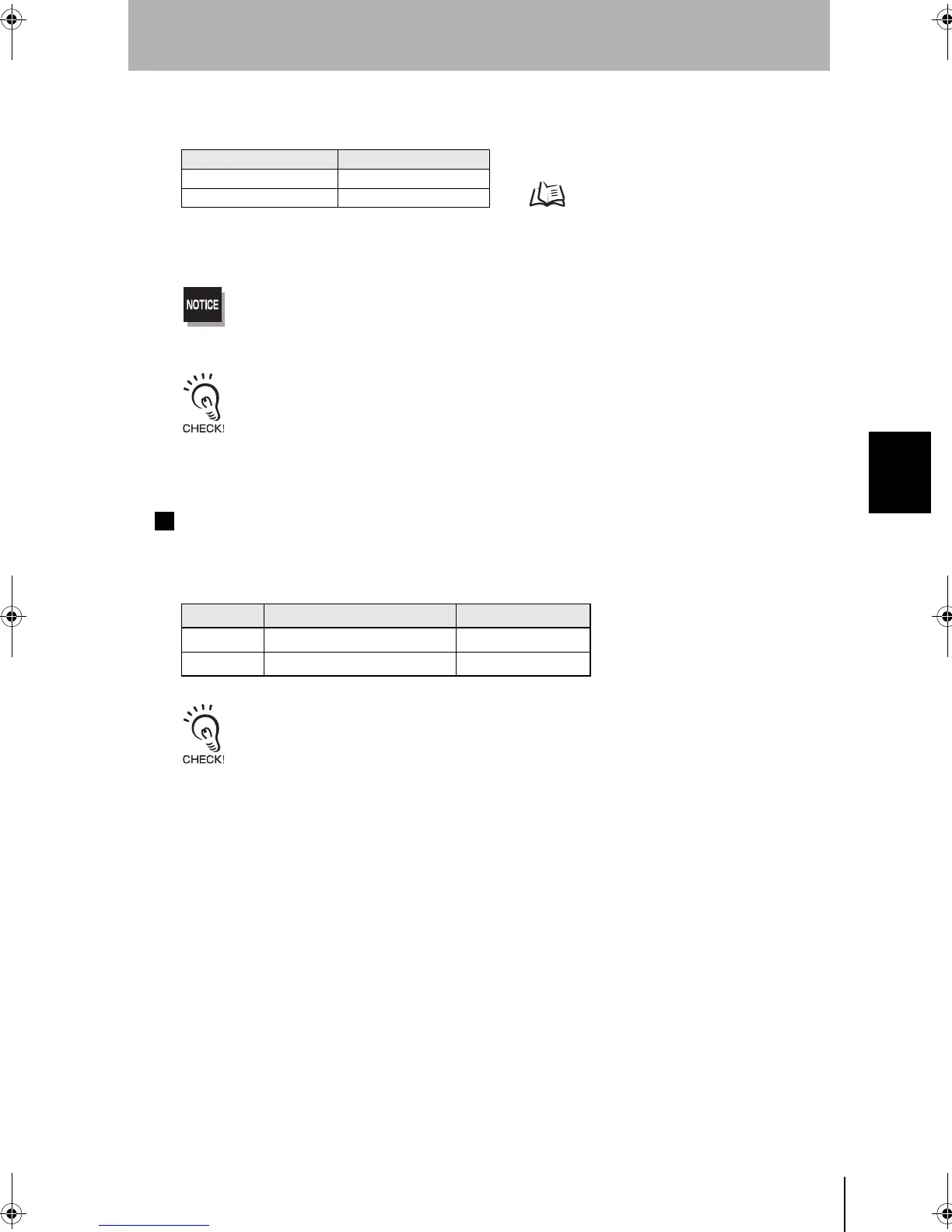
Strobe trigger output Signal
Camera 0 STGOUT0(A8)
Camera 1 STGOUT1(B8)
Connecting a Strobe Device p.76
F210setUP.book41ページ2003年1月28日 火曜日 午前11時6分