40
SECTION 4
Parallel Connection Methods
F210
Setup Manual
SECTION 4
Connecting External Devices
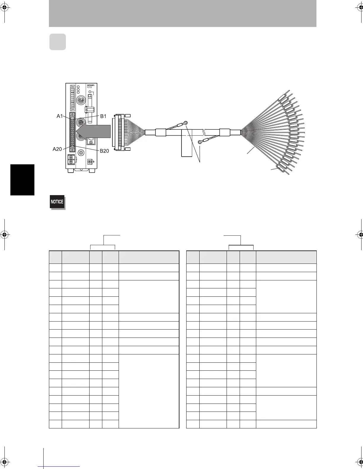
I/O Connector
Use an F160-VP Parallel I/O Cable (sold separately) to connect the Controller to external
devices. Align the connectors and insert the cable’s connector straight into the Controller’s
parallel connector. Tighten the connector’s mounting screws to secure the connection.
Turn OFF the power supply before connecting or disconnecting a Parallel I/O Cable. Peripheral devices may be
damaged if the cable is connected or disconnected with the power ON.
The parallel connectors are capped with screw-on covers when the Controller is shipped.When the connector is
not being used, leave the cover in place or replace the cover to protect against dust, dirt, and static electricity.
Pin Signal
Wire
Color
Mark
(Black)
Function Pin Signal
Wire
Color
Mark
(Red)
Function
A1 RESET
Lt.
brown
■
Restarts the Controller B1 COMIN
Lt.
brown
■
Common for input signals
A2 STEP
Yellow
■
Measurement trigger signal input
B2 DSA
Yellow
■
Inputs data send request signals
A3 DI0
Green
■
Command input
B3 DI1
Green
■
Command input
A4 DI2
Gray
■
B4 DI3
Gray
■
A5 DI4
White
■
B5 DI5
White
■
A6 DI6
Lt.
brown
■■
B6 DI7
Lt.
brown
■■
A7 DI8
Yellow
■ Command input expansion
B7 DI9
Yellow
■■
Command input expansion
A8 STGOUT0
Green
■
Strobe trigger 0 output(See note 1.)
B8 STGOUT1
Green
■■
Strobe trigger 1 output(See note 1.)
A9 RUN
Gray
■■
ON while in Run mode B9 ERROR
Gray
■■
ON when there is an
error.
A10 BUSY
White
■■
ON during processing B10 GATE
White
■■
ON for the set output time
A11 OR
Lt.
brown
■■■
Combined judgement result
B11
COMOUT1
Lt.
brown
■■■
Common for output signals (See note 2.)
A12 DO0
Yellow
■■■
Data output
B12 DO1
Yellow
■■■
Data output
A13 DO2
Green
■■■
B13 DO3
Green
■■■
A14 DO4
Gray
■■■
B14 DO5
Gray
■■■
A15 DO6
White
■■■
B15 DO7
White
■■■
A16 DO8
Lt.
brown
■■■■
B16
COMOUT2
Lt.
brown
■■■■
Common for DO0 to DO7
A17 DO9
Yellow
■■■■
B17 DO10
Yellow
■■■■
Data outputA18 DO11
Green
■■■■
B18 DO12
Green
■■■■
A19 DO13
Gray
■■■■
B19 DO14
Gray
■■■■
A20 DO15
White
■■■■
B20
COMOUT3 White
■■■■
Common for DO8 to DO15
Parallel I/O Cable
F160-VP (2m)
FG terminals
Ground to 100 Ω.
Wire Color
Pin Number
and Mark
Each wire of the F160-VP Parallel I/O Cable
has a unique wire-color/mark combination.
F210setUP.book40ページ2003年1月28日 火曜日 午前11時6分