44
SECTION 4
Connecting through the Serial Interface
F210
Setup Manual
SECTION 4
Connecting External Devices
1:1 Connection (Host Link)
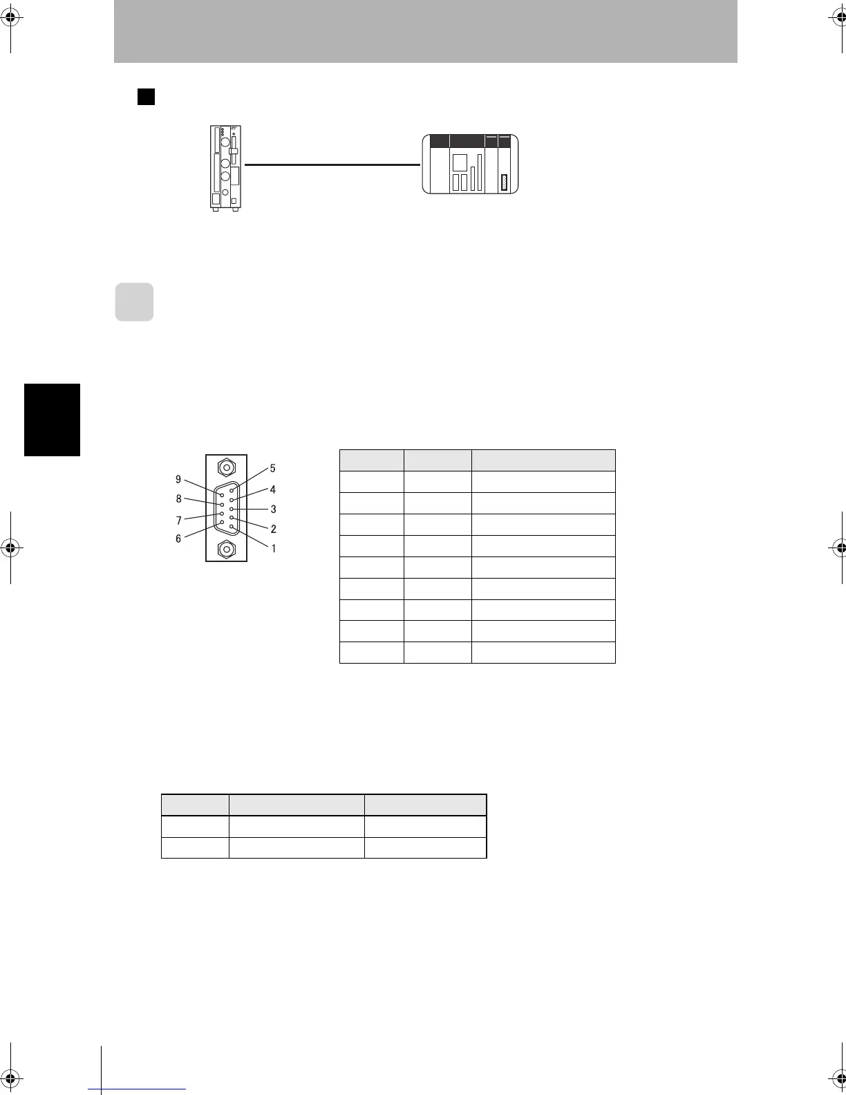
Connector
The Controller’s RS-232C/RS-422 Connector is a 9-pin D-SUB female connector.
The pin allocation is shown below.
A parallel I/O cable can be assembled using the following connector and cover or equivalent
components.
Pin Signal Function
1 FG Protective frame ground
2 SD For RS-232C
3 RD For RS-232C
4 NC Not connected
5RDB(+)For RS-422
6 RDA(-) For RS-422
7 SDB(+) For RS-422
8SDA(-)For RS-422
9 GND Signal ground
Recommended Model
Manufacturer Item
Plug OMRON Corporation XM2A-0901
Hood OMRON Corporation XM2S-0911
PLC
RS-232C cable
Controller
F210setUP.book44ページ2003年1月28日 火曜日 午前11時6分