A
F
C
D
E
B
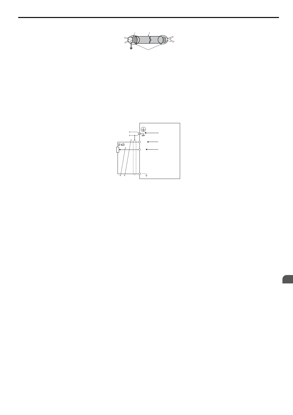
A – Drive side
B – Connect shield to ground terminal of drive.
C – Insulation
D – Control device side
E – Shield sheath (Insulate with tape)
F – Shield
Figure 3.14 Preparing the Ends of Shielded Cables
When
setting the frequency by analog reference from an external potentiometer, use shielded twisted-pair wires and ground
the shield of twisted-pair wires to the ground terminal of the drive.
NOTICE: The analog signal lines between the drive and the operator station or peripheral equipment should not exceed 50 meters
when using an analog signal from a remote source to supply the frequency reference. Failure to comply could result in poor system
performance.
+V
A1
AC
A
B
C
D
A – Drive
B
– Ground terminal (shield connection)
C – (+V) Frequency setting power source +10.5 Vdc
maximum 20 mA
D – (A1) Main speed frequency reference 0 to +10
Vdc (20 kΩ)
or
4 to 20 mA (250 Ω)/
0 to 20 mA (250 Ω)
Figure 3.15 Wiring the Frequency Reference to the Control Circuit Terminals (External Reference)
3.7 Control Circuit Wiring
SIEP C710606 33A OYMC AC Drive – J1000 User Manual
43
3
Electrical Installation