5-1 Connecting to Host Via Ethernet
Set the upper digit using the top rotary switch and the lower digit using the bottom rotary
switch.
The factory setting is 01.
When using automatic generation to convert addresses, set the node number to the same
value as that of the rightmost byte of the local IP address. If the same values cannot be set,
the IP address table method or combination method must be used to convert the addresses.
Setting Local IP Addresses
For CJ-series Ethernet Units, set the local IP address from the CX-Programmer or other
Support Software for the CPU Unit. Refer to the SYSMAC CS/CJ Series Ethernet Unit Opera-
tion Manual (W343) for details on setting methods.
CJ1W-ETN11
CS1W-ETN21
This is the connector used to connect the twisted-pair cable to the Ethernet.
•
•
Electrical Characteristics: Conforms to IEEE802.3 standards.
Connector Layout: RJ45 8-pin modular connector (conforms to ISO8877).
1
8
Connec-
tor Pin
Signal name
Abbreviation
Signal direction
1 Send data TD+ Output
2 Send data − TD− Output
3 Receive data + RD+ Input
4 Not used. − −
5 Not used. − −
6 Receive data − RD− Input
7 Not used. − −
8 Not used. − −
• CV/CVM1-series (-V@) PLCs
Unit for CV500-CPU01-V1, CV1000-CPU01-V1, CV2000-CPU01-V1, CVM1-CPU01-V2,
CVM1-CPU11-V2, and CVM1-CPU21-V2 CPU Units:
CV500-ETN01
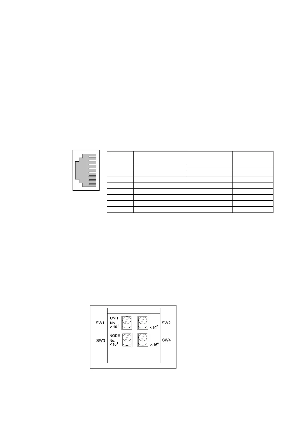
Setting Rotary Switches
Set the unit number and node number with the two rotary switches on the front of the Unit.
Switch Layout
The layout of the two switches is shown in the following diagram.
5-12
 Loading...


