3-3 Connecting the CX-Designer
3-3 Connecting the CX-Designer
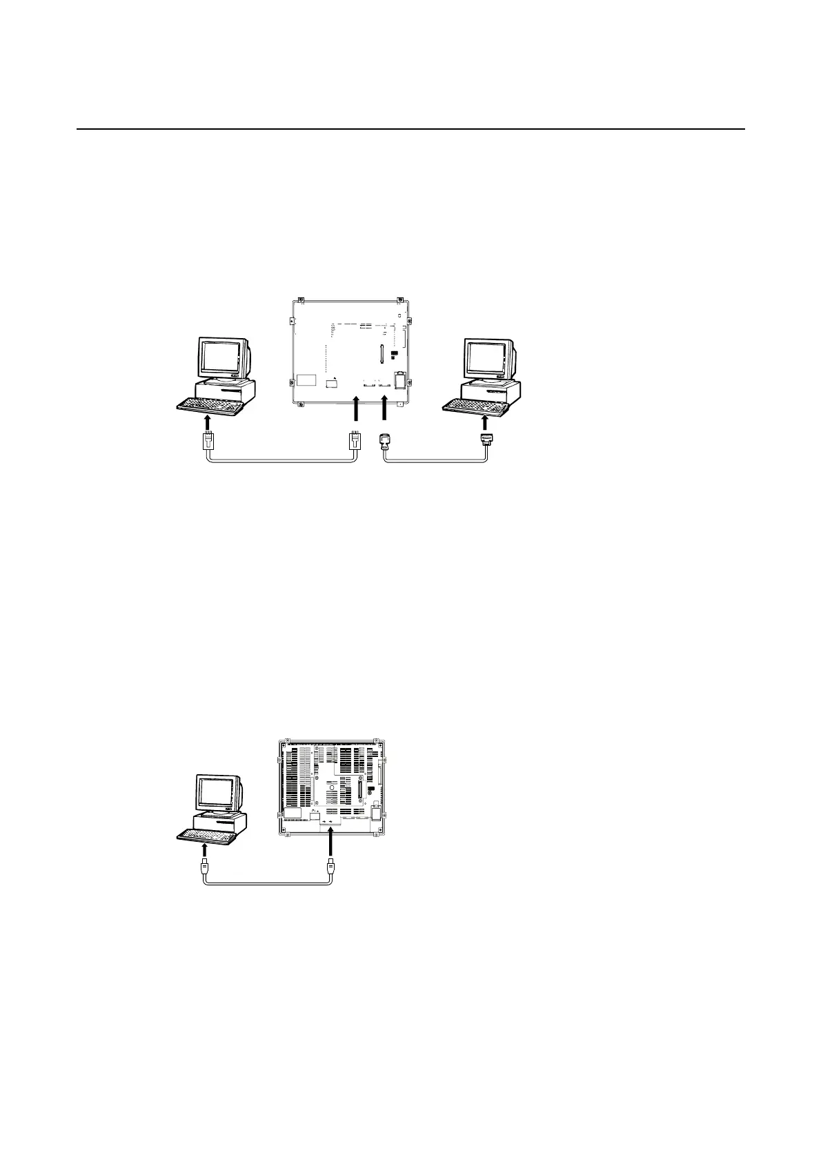
Use an RS-232C, Ethernet, or USB cable to connect the PT and computer so that screen
data that has been created with the CX-Designer can be transferred to the PT. A modem can
also be used.
3-3-1 Connecting via RS-232C or Ethernet
Connect the RS-232C cable from the computer to serial port A or B. The cable can be con-
nected to either serial port A or B, but cables cannot be connected to both ports at the same
time.
To use Ethernet, connect the Ethernet port on the computer to the Ethernet port on the PT.
• Communications Conditions
The communications conditions are set with the CX-Server. For details, refer to Transferring
Data to the PT in the CX-Designer’s Online Help.
• Recommended Connecting Cables
The following cables are recommended when connecting via RS-232C.
XW2Z-S002 (OMRON, cable length: 2 m)
(D-Sub male 9-pin and D-Sub female 9-pin, for IBM PC/AT or compatible computers
and NX computers in the PC-9800 Series)
For details on preparing connecting cables, refer to Appendix 5 Preparing Connecting Cables.
3-3-2 Connecting via USB
Connect the USB port on the computer to the USB slave connector on the PT. Some prepara-
tions are required and some restrictions exist, as described below. Be sure to connect USB
correctly.
24V
DC
HOST SLAVE
ETHERNET
PORT @B
PORT @A
RESET
SW
System Program Version
The system program version installed in the PT must be version 6.2 or higher. Update to ver-
sion 6.2 or higher if the current version is 6.1 or lower.
USB Driver for PTs
To transfer screens using USB communications, a USB driver for the PT must be installed in
the computer. For details on installing the USB drivers, refer to 2-4 Installing USB Drivers for
NS-series PTs in the CX-Designer User’s Manual.
3-12
 Loading...


