Appendix 3 Using NS-AL002 Converters
A-3-4 DIP Switch Settings
The NS-AL002 Adapter has four DIP switch pins for setting the RS-422A communications
conditions.
Set the DIP switch pins before connecting the cables to the Adapter.
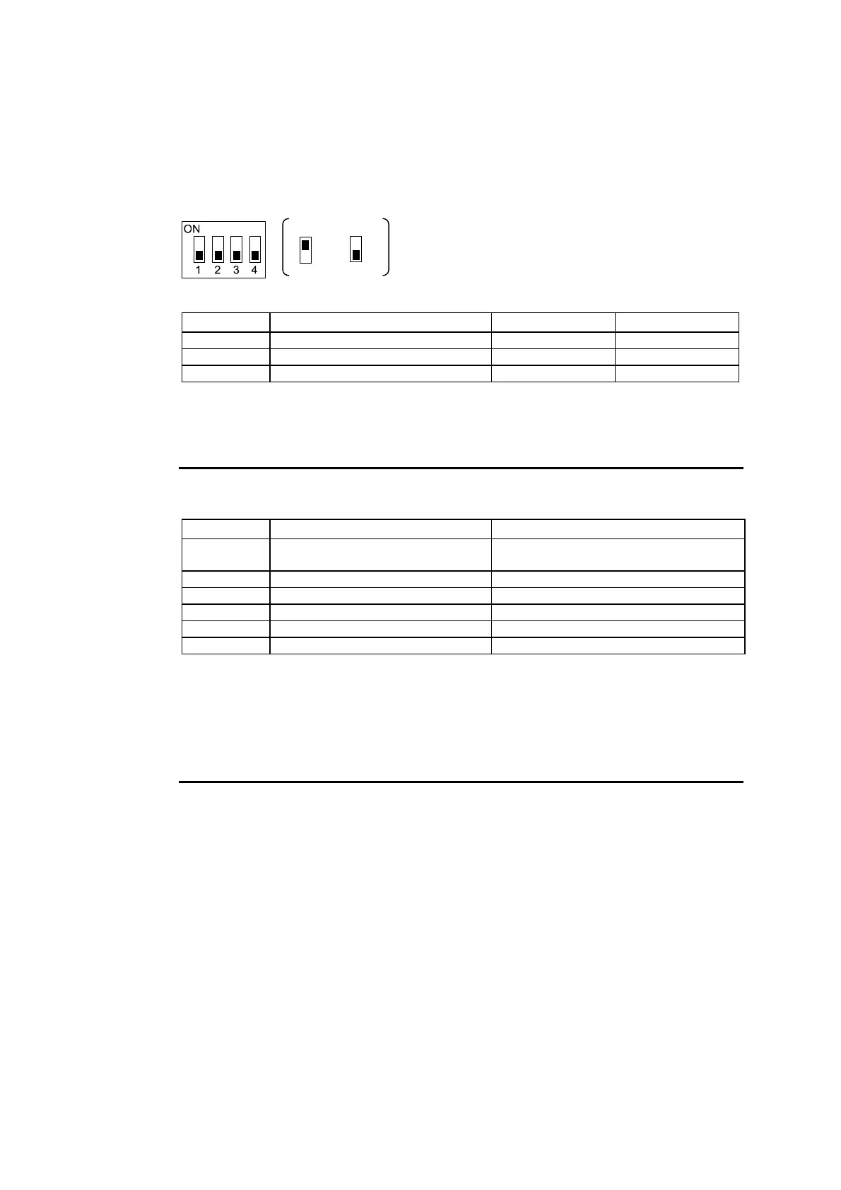
ON
OFF
DIP switch
The factory setting for the DIP switch is all pins set to OFF.
Pin Function ON OFF
Pin 1 Transmission mode RS/CS control Normal transmission
Pins 2 and 3 Two-wire/four-wire method selection Two-wire method Four-wire method
Pin 4 Terminating resistance Yes None
For 1:1 NT Link, set the RS-422A transmission mode to normal transmission (pin 1 OFF).
For 1:N NT Links (normal, high speed), set the RS-422A transmission mode to RS/CS
control (pin 1 ON).
Note
• Use the following DIP switch settings when connecting a CJ1W-CIF11 Conversion
Adapter to the PT.
Pin Function Setting
Pin 1 Terminating resistance selection ON: Terminating resistance enabled
OFF: Terminating resistance disabled
Pin 2 Two-wire/four-wire method selection OFF (four-wire)
Pin 3 Two-wire/four-wire method selection OFF (four-wire)
Pin 4 Not used. OFF
Pin 5 Selection of RS control for RD OFF (no RS control)
Pin 6 Selection of RS control for SD ON (RS control)
• When a CJ1W-CIF11 Conversion Adapter is used, the total transmission length is 50 m.
• If NT-001/NT-002 Link Adapters are used together with CJ1W-CIF11 Conversion Adapt-
ers on the same transmission path, the total transmission length is also 50 m.
• For details, refer to the Appendix G in the SYSMAC CJ Series Operation Manual
(W393).
• Make sure that both of the mounting screws on the D-Sub connector are tightened to a
torque of 0.3 N⋅m.
A-19
 Loading...


