5-2 Connecting to the Host Using Controller Link
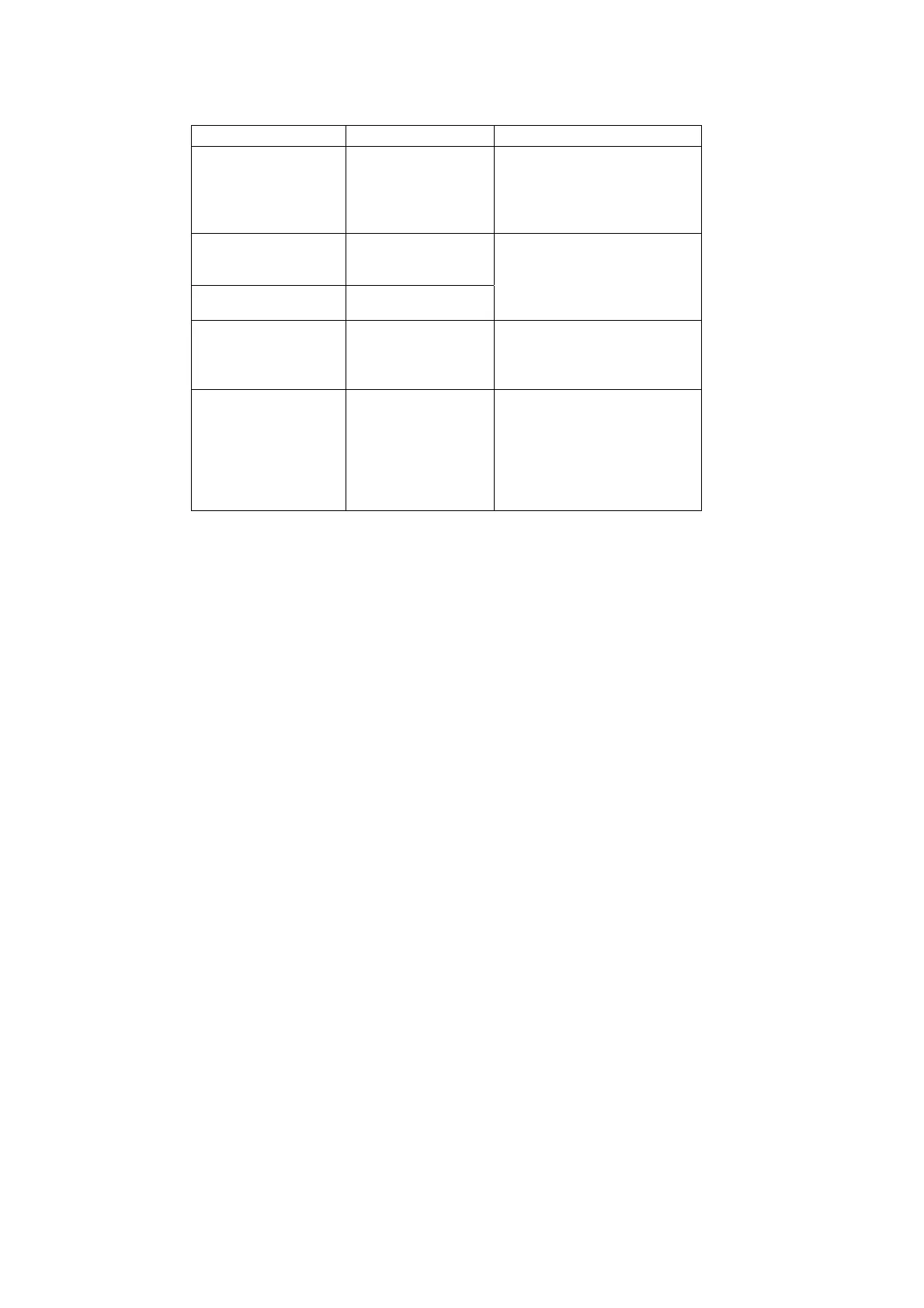
Device Model Remarks
Controller Link Unit
(See note.)
CVM1-CLK21
C200HW-CLK21
CS1W-CLK21
CQM1H-CLK21
CJ1W-CLK21
Required to connect PLC with
Controller Link Network.
Controller Link Sup-
port Board (ISA
Bus/PC98)
3G8F5-CLK21
3G8F6-CLK21
Controller Link Sup-
port Board (PCI Bus)
3G8F7-CLK21
Required to connect IBM
PC/AT or compatible com-
puters with Controller Link
Network.
Twisted-pair Cable ESVC0.5×2C Required to connect the PT,
PLC, and IBM PC/AT or com-
patible computers. Use
shielded twisted-pair cable.
Controller Link Wired
Relay Terminal Block
CJ1W-TB101 Used as a relay terminal block
for wires and can be used as
required to facilitate replace-
ment and maintenance of
Controller Link Units and
Boards after the communica-
tions system has been started.
Note: For details on the CPU Units that support connection to Controller Link Units, refer to Appendix
8 Standard Models.
5-2-2 Data Links
This section outlines data links and the method of setting data link tables when using data
links. For details, refer to the Controller Link Support Board Operation Manual (W307), Con-
troller Link Unit Operation Manual (W309), and the Controller Link Support Board for PCI Bus
Operation Manual (W383).
What Are Data Links?
Data links automatically exchange preset data between nodes (i.e., between PLCs, between
a PLC and an IBM PC/AT or compatible computer, or between a PLC and an NS-series PT).
Data links can be freely created for CS-series PLCs, C200HX/HG/HE PLCs, CVM1, CV-
series PLCs, CJ-series PLCs, CQM1H-series PLCs, and NS-series PTs.
Two data link areas, area 1 and area 2, can be set for each node. Data links can be set in ei-
ther of the following ways.
•
•
Data link areas can be set by inputting data link tables through the Controller Link Support
Software. Data link tables are created to define the data links. These tables enable free al-
location of data link areas.
Data links can be set automatically from a Programming Device. With automatically set data
links, all link areas are the same size.
Automatic setting and manual setting cannot be used together in the same network.
The following rules apply to these methods of setting data links.
1. Data links are enables concurrently for area 1 and area 2.
2. Separate settings (data link start words and send area size) are made in area 1 and area
2. The sequences of send and receive words are the same in area 1 and area 2.
3. Not all nodes must participate in the data links.
5-16
 Loading...


