2-12SectionInputting Numeric Values
199
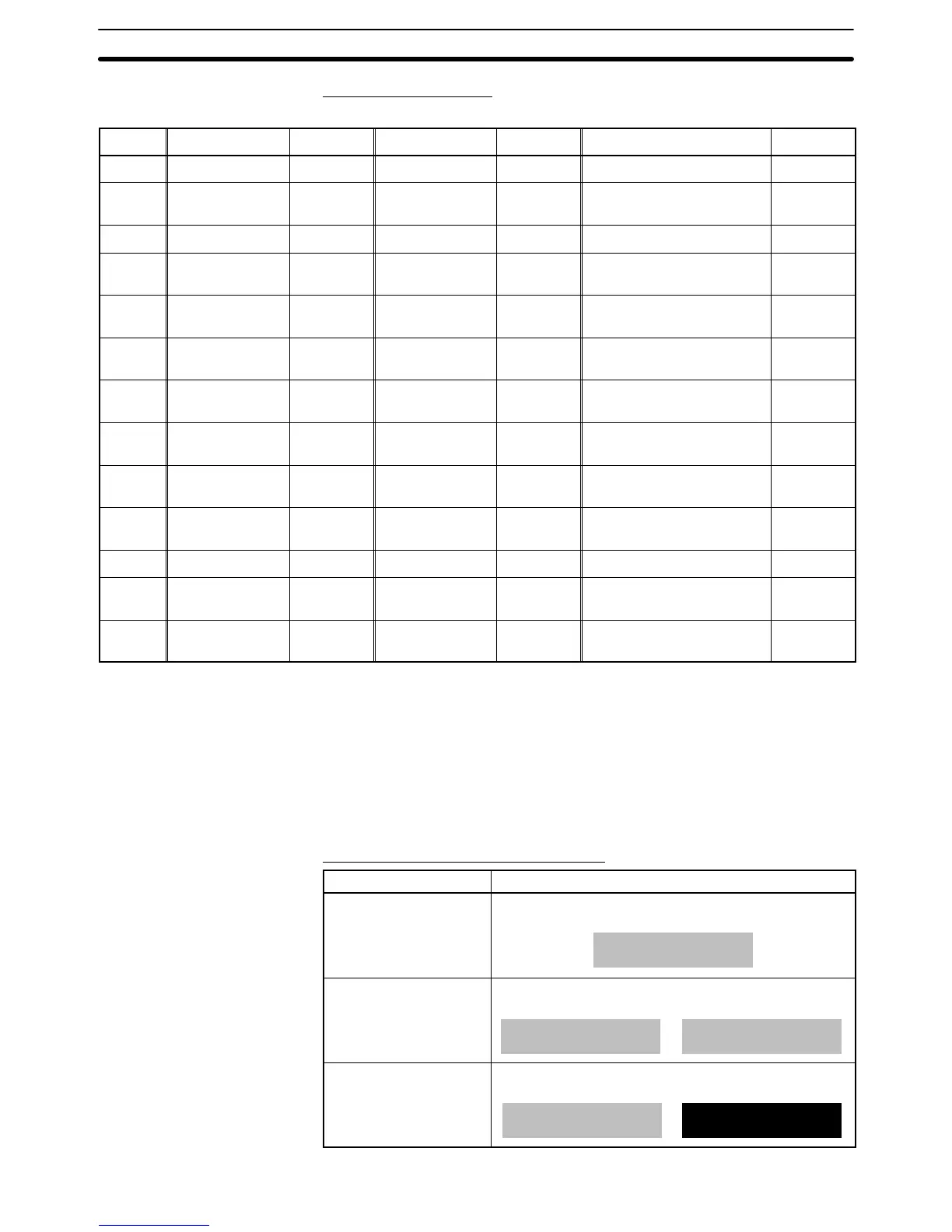
Interlock Bit Allocation
Interlock bits can be allocated in the following host (PC) areas.
Symbol C-series PCs Allocation CV-series PCs Allocation CS/CJ-series PCs Allocation
None IR Area OK CIO Area OK CIO Area OK
H HR Area OK --- --- HR Area
Not with
Host Link
A AR Area OK Auxiliary Area No AR Area OK
L LR Area OK --- --- LR Area
*1
Not with
Host Link
T
TC Area,
Timer PVs
No
Timer Area,
Timer PVs
No
TC Area,
Timer PVs
No
TU --- --- --- ---
TC Area,
Timer Completion Flags
Not with
Host Link
C
TC Area,
Counter PVs
No
Counter Area,
Counter PVs
No
TC Area,
Counter PVs
No
CU --- --- --- ---
TC Area,
Counter Completion Flags
Not with
Host Link
W --- --- --- --- WR Area
Not with
Host Link
TK --- --- --- --- Task Flags
Not with
Host Link
D DM Area OK DM Area OK DM Area OK
E
EM Area
*2
,
current bank
OK
EM Area,
current bank
Not with
Host Link
EM Area,
current bank
Not with
Host Link
E0_ to
EC_
--- --- --- ---
EM Area,
EM banks 0 to C
Not with
Host Link
*1: LR 00000 to LR 00199 are converted to CIO 01000 to CIO 01199.
*2: The EM Area is supported only by the C200HX/HG/HE(-Z)E PCs.
Since the Auxiliary Area of the CVM1/CV-series PCs is allocated to system func-
tions, and it cannot be used for purposes other than system use.
The range of each memory area differs according to the PC. Refer to Appendix D
PC Memory Maps on page 435.
When a DM Area or EM Area address is specified, add a bit number (00 to 15) to
the end of the word address.
Display Attributes and Drawing Result
Attribute Drawing Result
Standard The character string input field is displayed with the
specified foreground color and background color.
12345678
Flash Repeated alternation of the standard display and no
display.
⇔
12345678
Inverse Flash Repeated exchange of the foreground color and
background color.
12345678
⇔
12345678