2-2SectionAreas for Control/Notification
53
Reference: The configuration and functions of the PT status control area are different when
the PT is set to NT20S or NT30/620 compatible mode. Refer to Appendix C for
details on the NT20S and NT30/620 compatible modes.
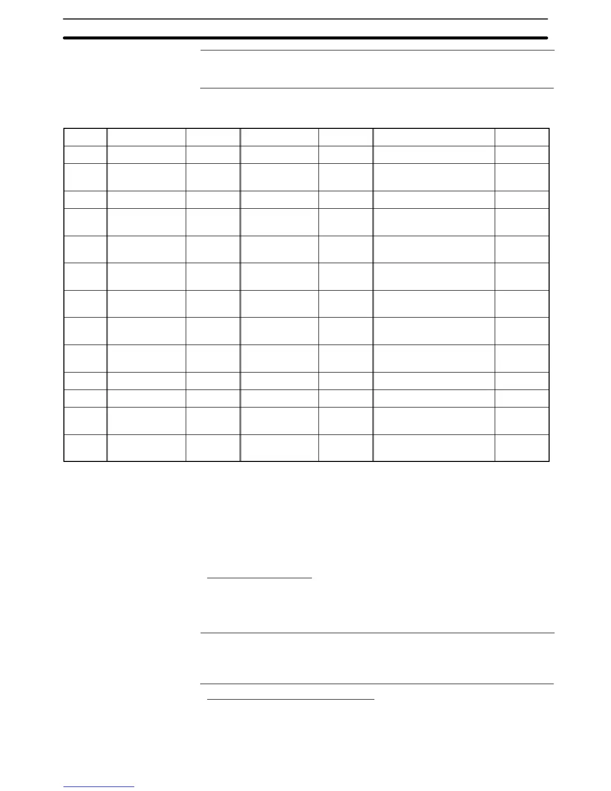
Words can be allocated for the PT status control area (host ↔ PT) in the follow-
ing host (PC) areas.
Symbol C-series PCs Allocation CV-series PCs Allocation CS/CJ-series PCs Allocation
None IR Area OK CIO Area OK CIO Area OK
H HR Area OK --- --- HR Area
Not for
Host Link
A AR Area OK Auxiliary Area No AR Area OK
L LR Area OK --- --- LR Area
*1
Not for
Host Link
T
TC Area,
Timer PVs
No
Timer Area,
Timer PVs
No
TC Area,
Timer PVs
No
TU --- --- --- ---
TC area,
Timer Completion Flags
No
C
TC Area,
Counter PVs
No
Counter Area,
Counter PVs
No
TC Area,
Counter PVs
No
CU --- --- --- ---
TC Area,
Counter Completion Flags
No
W --- --- --- --- WR Area
Not for
Host Link
TK --- --- --- --- Task Flags No
D DM Area OK DM Area OK DM Area OK
E
EM Area
*2
,
current bank
OK
EM Area,
current bank
Not for
Host Link
EM Area,
current bank
Not for
Host Link
E0_ to
EC_
--- --- --- ---
EM Area,
EM banks 0 to C
Not for
Host Link
*1: LR 00000 to LR 00199 are converted to CIO 01000 to CIO 01199.
*2: The EM Area is supported only by the C200HX/HG/HE(-Z)E PCs.
The Auxiliary Area of the CVM1 and CV-series PCs is allocated to system func-
tions, and cannot be used for purposes other than system use.
The range of each memory area differs according to the PC. Refer to Appendix D
PC Memory Maps on page 435.
Functions of the PT Status Control Area
Screen Switch Setting
Data is written to the screen switch setting word from both the PT and the host.
The meaning of the data differs according to whether it is written from the PT or
the host. However, if the PT is currently operating, the number of the screen dis-
played is always written to the screen switch setting word.
Reference: When the PT is set to NT20S or NT30/620 compatible mode, data can be written
from the host only. In this case, the screen switch setting notification from the PT
occurs in the first word (word m) of the PT status notify area. Refer to Appendix C
for details on the NT20S and NT30/620 compatible modes.
When Data Is Written from the Host
To switch the screen displayed at the PT by an instruction from the host, write the
screen number, as a 4-digit BCD or hexadecimal value, to the screen switch set-
ting word. Whether the value is expressed in BCD or hexadecimal is determined
Words Allocated for the
PT Status Control Area