EasyManua.ls Logo

Omron NT21 User Manual

Omron NT21
480 pages
To Next Page IconTo Next Page
To Previous Page IconTo Previous Page
Page #400 background imageLoading...
Page #400 background image
4-3SectionCommands/Responses
385
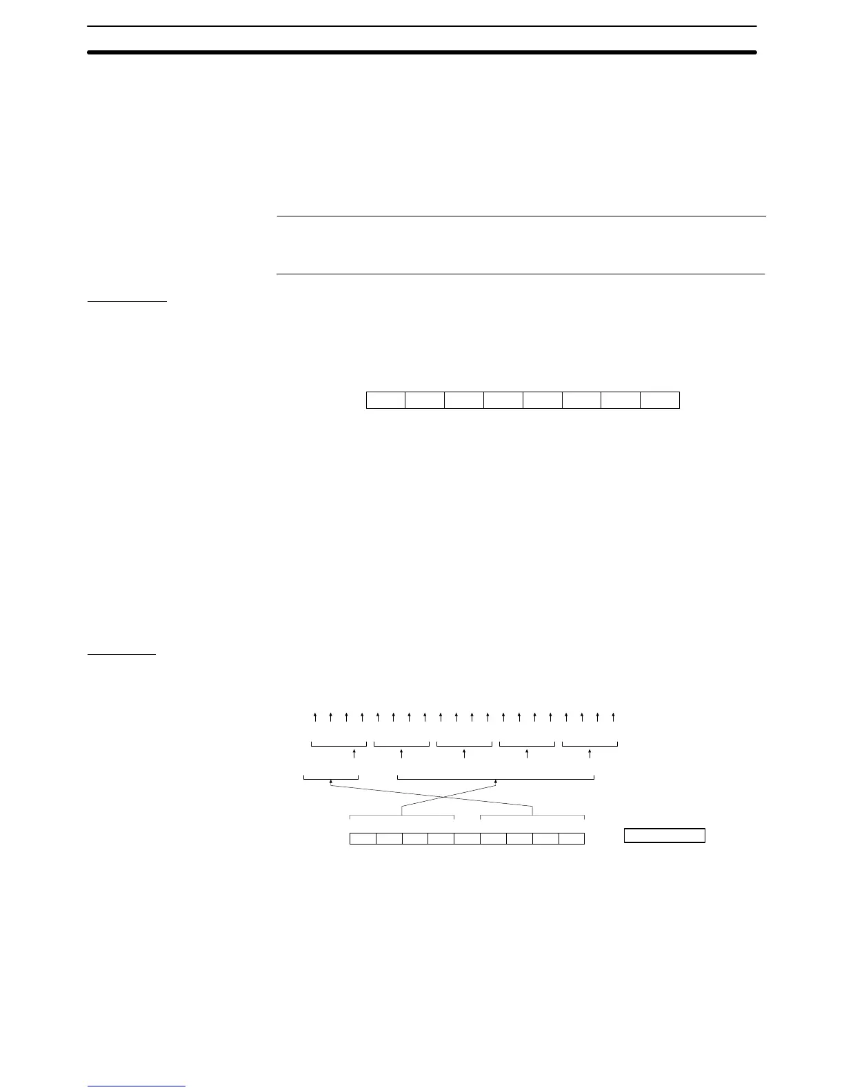
specified as 4 hexadecimal digits value. (Table entries with
smaller number is the rightmost bit.)
If written data is less than 16, the specification is started from bit
0. (Remaining leftmost bit will be ignored.)
The bit memory table data (4 hexadecimal digits) is delimited by
commas by each 16 table entries.
s
1
, s
2
: Checksum (2 hexadecimal digits)
When m is 0 or 8, omit this setting.
Reference: The maximum number that can be specified for bit memory table entries de-
pends on the setting for numbers of bit memory table entries (256/1000) made at
the Support Tool.
Response
Only if Yes is set for the Response memory switch, the response indicated below
is returned on normal completion.
Format
1B 57
[ESC] [CR]W
3430 31 0D42
B
30
0 0 s1 s2
s
1
, s
2
: Checksum (2 hexadecimal digits)
This is always added (fixed as 14H)
Function
Writes the data of the specified number of bit memory table entries, starting
from the specified bit memory table entry.
A maximum of 100 table entries can be written at one time.
If a number of table entries that is not a multiple of 16 is specified, 0 is inserted
in remaining bits (leftmost bits).
The number (n) of 4 hexadecimal digits value to be specified is as follows:
n=(number of written bit memory table entries–1)\161
(\ indicates the subtraction of the integer.)
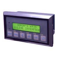
Example
Writing bit memory table entries 51 to 70
Contents to be written to bit
memory
Changing to Bit data
Changing to Hexadecimal
(Remaining left most bit 0)
Data to be specified
ASCII code
68 67 66 65 64 63 62 61 60 59 58 57 56 55 54 53 52 51
ON ON ON OFF ON ON OFF ON ON OFFOFF ON OFFOFFOFFOFF ON ON
111011011001000011
F B 6 4 3000
46
F
30
0
30
0
30
0
2C
,
33
3
34
4
36
6
42
B
70 69
ON ON
11

Table of Contents

Other manuals for Omron NT21

Questions and Answers:

Omron NT21 Specifications

General IconGeneral
Display TypeSTN monochrome LCD
Display Size5.7 inches
Resolution320 x 240 pixels
Touch PanelAnalog resistive
Communication PortsRS-232C, RS-422/485
Power Supply24 VDC
Operating Temperature0 to 50°C
Storage Temperature-20 to 60°C
Weight0.8 kg
Memory512 KB

Summary

SECTION 1 General

1-1 Role and Operation of the PT

Introduces the fundamental role and operation of Programmable Terminals (PTs).

1-2 Functions of the NT21, NT31/NT31C and NT631/NT631C

Details the features, comparisons, and principal functions of the NT series terminals.

1-3 System Configuration

Explains the system configuration and peripheral devices connectable to the PTs.

1-4 Communications with the Host

Covers various communication methods for connecting the PT to a host system.

1-5 Communication by Using Memory Links

Describes communication using memory links, a method other than direct connection.

1-6 Before Operating

Provides essential steps and considerations before operating the PT.

SECTION 2 PT Functions

2-1 PT Screens

Describes the PT screens which form the basis of PT functions.

2-2 Areas for Control/Notification

Explains the areas provided for PT control and status notification between PT and host.

2-7 Touch Switches

Details input from the touch panel, allowing screen switching and bit information transmission.

2-11 Alarm List, Alarm History

Explains monitoring host bits and displaying messages or image/library data when a bit changes to ON.

2-12 Inputting Numeric Values

Details the procedure for inputting numeric values using numeral input fields or thumbwheel switches.

2-13 Inputting Character Strings

Explains inputting character strings using touch switches or a bar code reader.

2-14 Recipes

Describes writing and reading data in table format to/from the host, allowing multiple settings to be managed.

2-16 Special Functions

Covers display history, alarm history, resume, screen saver, buzzer, clock, print, contrast/brightness, programming console, and device monitor.

2-17 Device Monitor Function

Details the Device Monitor function for reading/changing PC data and displaying PC error logs.

SECTION 3 How to Use the PT

SECTION 4 Using Memory Link

SECTION 6 Troubleshooting and Maintenance

6-1 Troubleshooting

Guides on actions to take when PT errors occur, by matching symptoms to remedies.

6-2 Responding to Displayed Error Messages

Details how to respond to various error messages displayed on the PT.

Appendix B Compatibility with Screen Data of Other PT Models

Appendix C NT20S and NT30/620 Compatible Modes

Related product manuals