2-2SectionAreas for Control/Notification
70
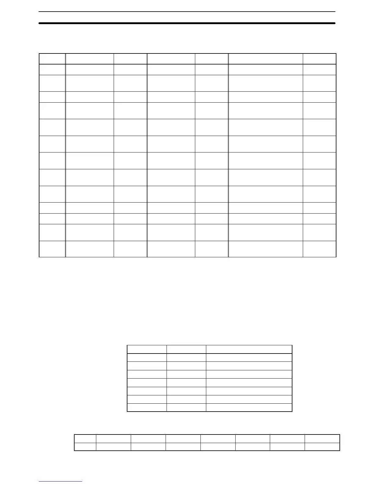
Words can be allocated for the clock data area (host to PT) in the following host
(PC) areas.
Symbol C-series PCs Allocation CV-series PCs Allocation CS/CJ-series PCs Allocation
None IR Area OK CIO Area OK CIO Area OK
H HR Area OK --- --- HR Area
Not for
Host Link
A AR Area OK Auxiliary Area No AR Area OK
L LR Area OK --- --- LR Area
*1
Not for
Host Link
T
TC Area,
Timer PVs
No
Timer Area,
Timer PVs
No
TC Area,
Timer PVs
No
TU --- --- --- ---
TC area,
Timer Completion Flags
No
C
TC Area,
Counter PVs
No
Counter Area,
Counter PVs
No
TC Area,
Counter PVs
No
CU --- --- --- ---
TC Area,
Counter Completion Flags
No
W --- --- --- --- WR Area
Not for
Host Link
TK --- --- --- --- Task Flags No
D DM Area OK DM Area OK DM Area OK
E
EM Area
*2
,
current bank
OK
EM Area,
current bank
Not for
Host Link
EM Area,
current bank
Not for
Host Link
E0_ to
EC_
--- --- --- ---
EM Area,
EM banks 0 to C
Not for
Host Link
*1: LR 00000 to LR 00199 are converted to CIO 01000 to CIO 01199.
*2: The EM Area is supported only by the C200HX/HG/HE(-Z)E PCs.
The Auxiliary Area of the CVM1 and CV-series PCs is allocated to system func-
tions, and cannot be used for purposes other than system use.
The range of each memory area differs according to the PC. Refer to Appendix D
PC Memory Maps on page 435.
The clock data that can be specified is listed in the following table.
Item Data (BCD) Remarks
Seconds 00 to 59
Minutes 00 to 59
Hour 00 to 23 24-hour time
Day of month 01 to 31
Month 01 to 12
Year 00 to 99 Rightmost two digits of year
Day of week 00 to 06 See following table.
Days of the week are expressed as follows:
Day Sunday Monday Tuesday Wednesday Thursday Friday Saturday
Value 00 01 02 03 04 05 06
Words Allocated for the
Clock Data Area