3 - 39
3 Part Names and Functions
NX-series Safety Control Unit User’s Manual (Z930)
3-3 Safety I/O Functions
3
3-3-2 Safety Output Functions
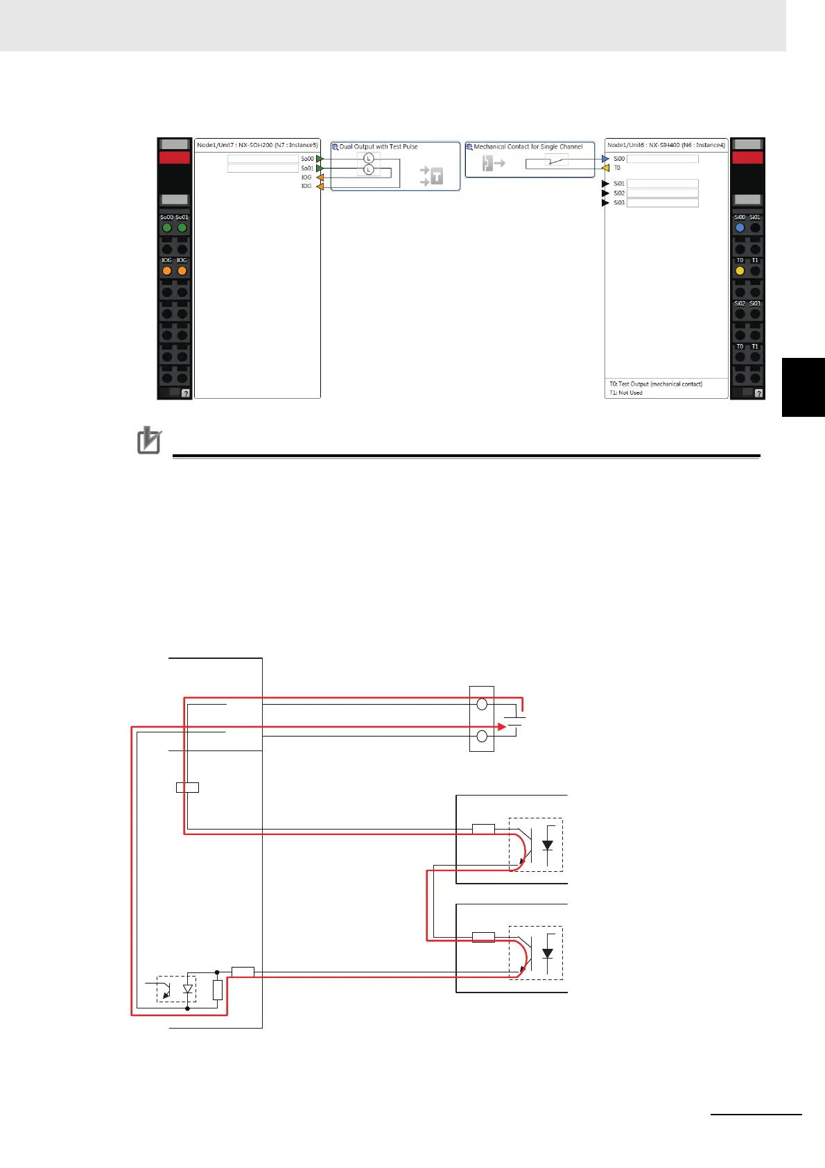
Example of Sysmac Studio Settings
Precautions for Correct Use
• If you directly connect more than one EDM terminal to one safety input terminal, the voltage
at the safety input terminal will be reduced proportionately to the number of connections.
When determining the number of direct connections, consider the voltage drop between the
EDM terminals in the design.
Formula
{I/O power supply − Test output ON residual voltage − Safety input ON voltage}/Residual
voltage between EDM terminals ≥ Number of direct connections
Theoretical Values
NX-SID800: Two Units max. per safety input terminal
NX-SIH400: Four Units max. per safety input terminal
Safety input ON voltage
TO to T1
Si0 to Si3 (Si0 to Si7)
Test output ON residual voltage:
1.2 V max.
NX-ECC
NX-SI
IOG
IOV
I/O power supply
(24 VDC): 20.4 to 28.8 V
NX-SIH400: 11 V min.
NX-SID800: 15 V min.
Residual voltage between
EDM+/EDM- terminals: 1.7 V max.
Residual voltage between
EDM+/EDM- terminals: 1.7 V max.
EDM+
R88D-K
EDM−
EDM+
EDM−
 Loading...


