3 Part Names and Functions
3 - 40
NX-series Safety Control Unit User’s Manual (Z930)
• If you branch connections to more than one SF terminal from one safety output terminal, the
load current at the safety output terminal will be increased proportionately to the number of
connections. When determining the number of branch connections, consider the input cur-
rent to the SF terminals in the design.
Formula
{Maximum load current per safety output terminal}/ {Input current per SF terminal} ≥ Num-
ber of branch connections
Theoretical Values
NX-SOD400: 50 Units max. per safety output terminal
NX-SOH200: 200 Units max. per safety output terminal
(In addition to the above, it is also necessary to consider the mounting directions, ambient
temperature, and Unit total load current.)
• The total wiring length from the safety output terminal to the output device (L1 + L2 + L3 + L4,
L5 + L6 + L7 + L8, L9 + L10 + L11 + L12, and L13 + L14 + L15 + L16) is 100 m max.
• The total wiring length of cables (L17 + L18 + L19 + L20 + L21) that can be connected to one
test output is 100 m max.
• Set the input device to Mechanical Contact Type to set the NX-SI EDM connection termi-
nals.
•An R88D-K Servo Drive can be used in a Safety Category 3 or lower or a PLd or lower
application. It cannot be used in a Safety Category 4 or PLe application.
• Refer to the following manuals for details on the safety function settings and the precautions
for the correct use of the R88D-K Servo Drive.
• AC Servomotors/Servo Drives G5-series with Built-in EtherCAT Communications User’s
Manual (Cat. No. I576)
• AC Servomotors/Servo Drives G5-series with Built-in EtherCAT Communications Linear
Motor Type User’s Manual (Cat. No. I577)
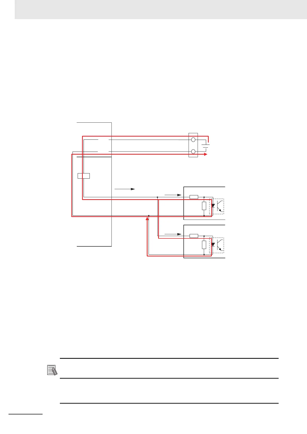
• A special connector (R88A-CNK81S) is required to connect the R88D-K.
• The wiring diagram shown above is an example that turns OFF four axes simultaneously.
Alternatively, each axis can be wired to a separate safety I/O terminal.
Safety output maximum load current
So0,2
IOG
NX-ECC
NX-S
O
IOG
IOV
I/O power supply
(24 VDC): 20.4 to 28.8 V
NX-SOH200: 2.0 A/point
NX-SOD400: 0.5 A/point
10 mA
max.
SF1+
R88D-K
SF1−
SF1+
SF1−
10 mA
max.
 Loading...


