4 - 3
4 Calculating Safety Reaction Times
NX-series Safety Control Unit User’s Manual (Z930)
4-1 Safety Reaction Times
4
4-1-2 Calculating Safety Reaction Times
Precautions for Correct Use
• If the safety task period changes due to changes in the safety program or other reasons,
recalculate the safety reaction times.
• To calculate the safety reaction times, add the delaying influences from the input filter delay
settings, the safety program function block delay settings, and the safety program loopback
connections.
Precaution for Conformance to ISO 13856-1:2013
If you use a UM Safety Mat to build a pressure-sensitive protective device that conforms to ISO
13856-1:2013 (Safety of machinery -- Pressure-sensitive protective devices -- Part 1: General prin-
ciples for design and testing of pressure-sensitive mats and pressure-sensitive floors), the
NX-series Safety Control Unit must meet the following condition in order to satisfy the requirement
for the specified reaction time.
• The value of the FSoE watchdog timer in the NX-SIH400 that is connected to the UM Safety Mat
must be 42 ms or less.
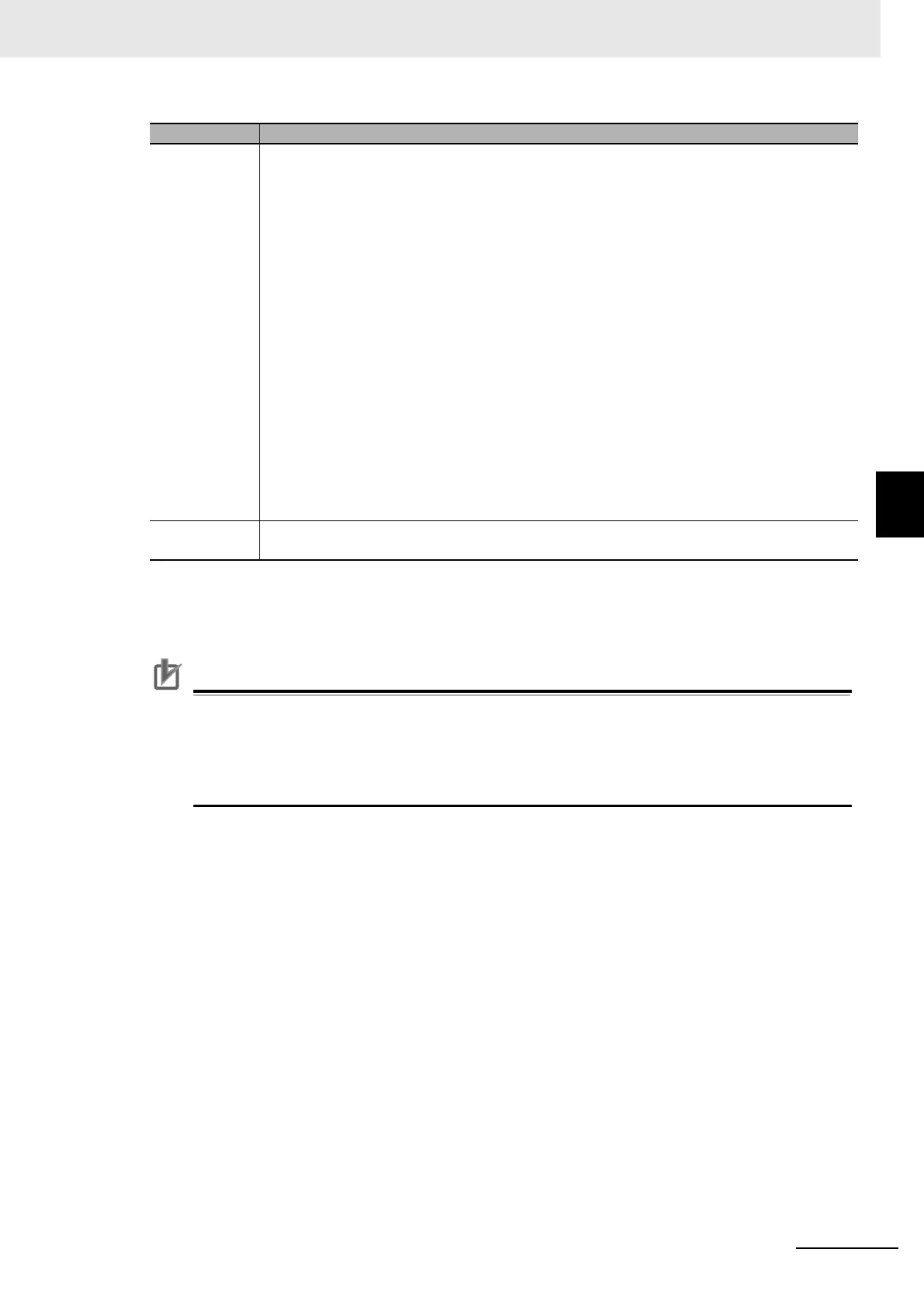
Safety I/O
refresh time
Calculate the sum of the following configuration elements. This is the time from when the safety
input terminal changes until the change goes through the Safety CPU Unit and the safety output
terminal turns OFF.
Calculation: Find the sum of the following configuration elements.
Safety I/O refresh time = Input delay time + Safety input refresh time + Safety output refresh
time
• The input delay time is the input OFF delay time that is set for the safety input terminal on the
Safety Input Unit.
• The safety input refresh time is the value of the FSoE watchdog timer between the Safety
CPU Unit and Safety Input Unit plus the Safety Input Unit’s processing time.
The processing times of the Safety Input Units are as follows:
NX-SIH400: 9 ms
NX-SID800: 5 ms
• The safety output refresh time is the value of the FSoE watchdog timer between the Safety
CPU Unit and Safety Output Unit plus the Safety Output Unit’s processing time.
The processing times of the Safety Output Units are as follows:
NX-SOH200: 1 ms
NX-SOD400: 1 ms
Actuator
response time
This is the response time that is required for an actuator, such as a safety relay, to turn OFF.
The value is defined for each actuator.
*1. The fault detection time for a 24 V short-circuit fault in a D40A Non-contact Door Switch is 18 ms. If usage is
for an application other than a Door Switch, use a safety sensor/switch response time of 18 ms.
*2. Refer to Precaution for Conformance to ISO 13856-1:2013 on page 4-3 for a precaution on conformance to ISO
13856-1:2013.
Time element Description
 Loading...


