6 System Configuration and Setup
6 - 6
NX-series Safety Control Unit User’s Manual (Z930)
8 Or, perform step 5 for the EtherCAT Coupler Unit that was added to display the Slave Terminal
Tab Page.
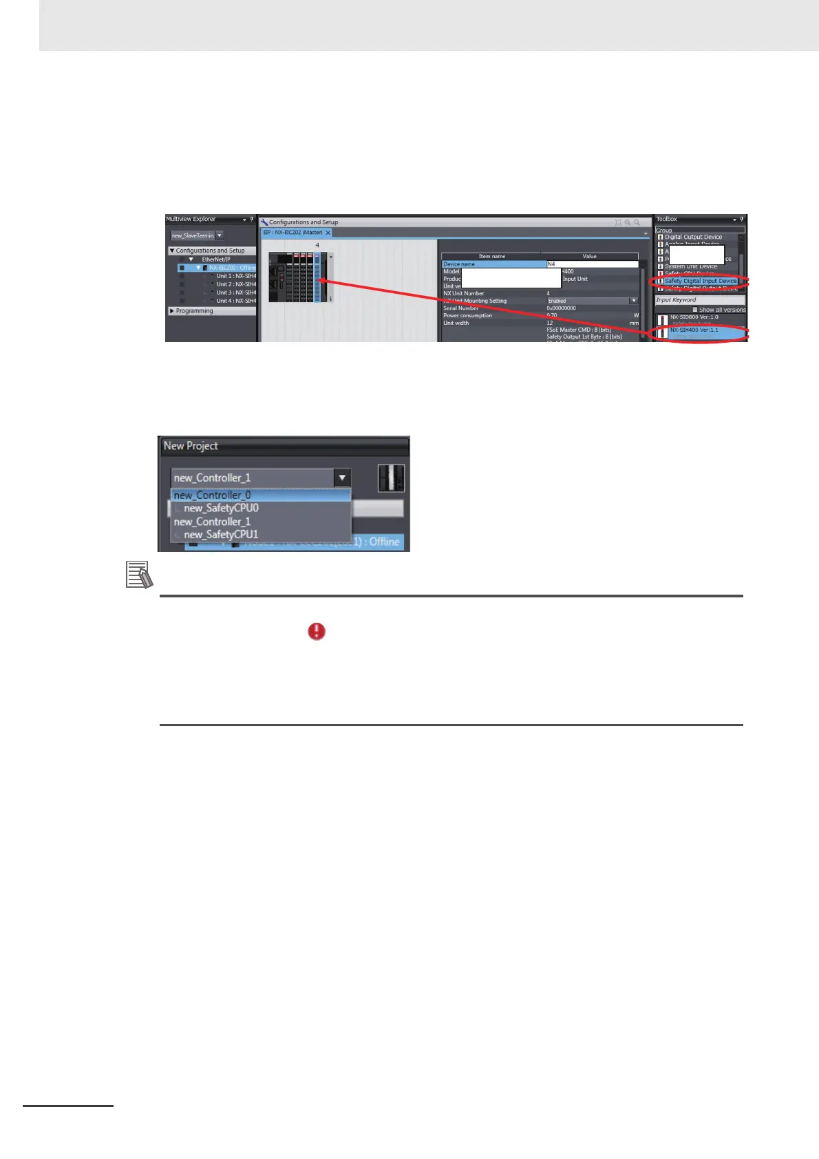
9 Select Safety Digital Input Device or Safety Digital Output Device from the Groups List in the
Toolbox. The Safety I/O Unit is displayed below it. Drag the Unit to the Slave Terminal and place
it in the configuration.
This completes the creation of the Controller configuration for an NJ/NX-series CPU Unit that includes
Safety Control Units. After the Safety CPU Unit is added to the NJ/NX-series Controller configuration, it
will be displayed in the Controller Selection Box in the Multiview Explorer. The Safety CPU Unit that
was added is displayed below the NJ/NX-series Controller (i.e., the EtherCAT master).
• Only one Safety CPU Unit can be placed on the EtherCAT network. If you add more than one
Safety CPU Unit, the icon is displayed under all of the Safety CPU Units and it will cause
an error during the build process.
• Refer to the NX-series EtherCAT Coupler Unit User’s Manual (Cat. No. W519-E1-02 or later)
for the number of NX Units that can be mounted to a Slave Terminal.
• Use the Multiview Explorer to move NX Units between Slave Terminals.
 Loading...


