3-16
3-1 Servo Drive Specifications
OMNUC G5-SERIES AC SERVOMOTOR AND SERVO DRIVE USER'S MANUAL
3
Specifications
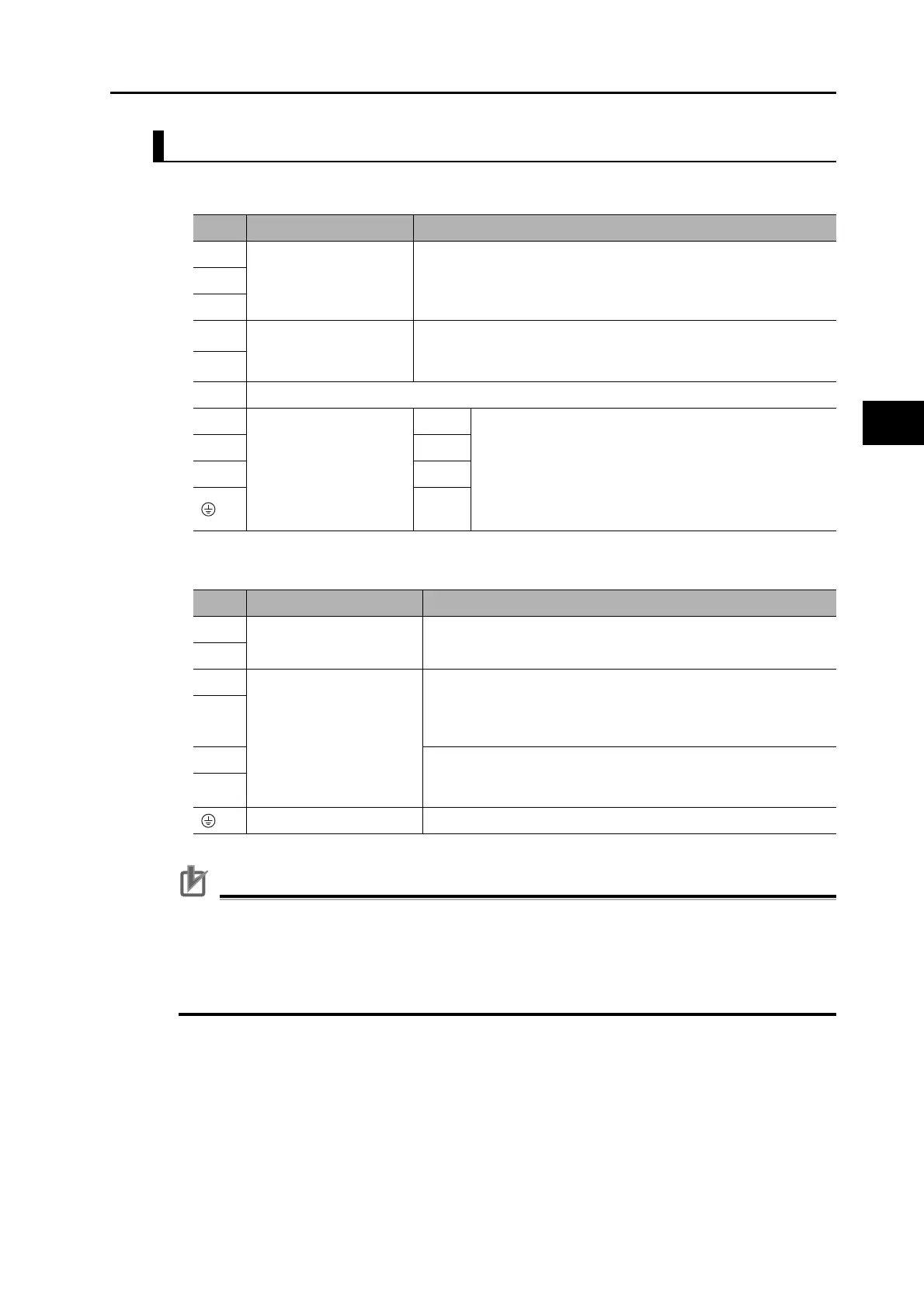
R88D-KT75F
Terminal Block Specifications, Left Terminal Block (TB1)
Terminal Block Specifications, Right Terminal Block (TB2)
Precautions for Correct Use
Tighten the terminal block screws to the torque of 1.5 N•m (M5).
If the torque for terminal block screws exceeds 2.0 N•m (M5), the terminal block may be damaged.
Tighten the fixing screw of the terminal block cover to the torque of 0.2 N•m (M3).
Tighten the ground screws to the torque of 1.4 to 1.6 N•m (M5).
Never connect an External Regeneration Resistor between the B1 and NC terminals
Symbol
Name Function
L1
Main circuit power supply
input
R88D-KT@F (7.5 kW): 3-phase 380 to 480 VAC (323 to 528 V) 50/
60 Hz
L2
L3
B1
External Regeneration
Resistor connection
terminals
Connect an External Regeneration Resistor between B1 and B2.
B2
NC Do not connect.
U
Motor connection
terminals
Red These are the output terminals to the Servomotor.
Be sure to wire them correctly.
VWhite
WBlue
Green/
Yellow
Symbol
Name Function
24 V Control circuit power
supply input
24 VDC±15%
0 V
DB1 Dynamic brake resistance
control terminals
These terminals are used to control the MC for externally
connected dynamic brake resistance. The output contact
specifications are 1 A max. at 300 VAC/100 VDC max. Connect
them if required.
DB2
DB3 Normally DB3 and DB4 are connected. When using an externally
connected Dynamic Brake Resistor, remove the short bar from
between DB3 and DB4.
DB4
Frame ground This is the ground terminal. Ground to 10 Ω or less.
 Loading...


