3-27
3-1 Servo Drive Specifications
OMNUC G5-SERIES AC SERVOMOTOR AND SERVO DRIVE USER'S MANUAL
3
Specifications
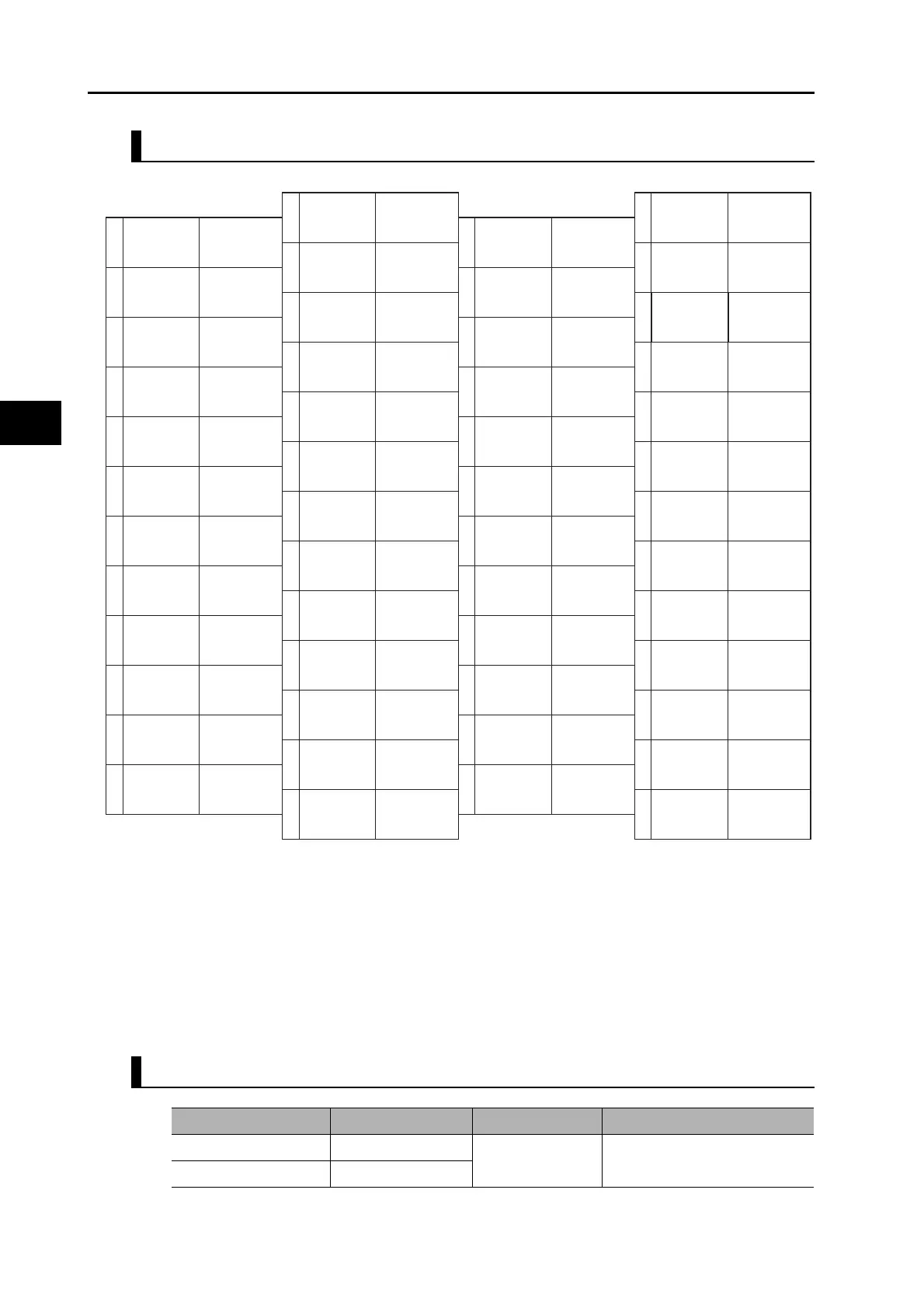
CN1 Pin Arrangement
Note.Do not connect anything to unused pins (*1).
For general-purpose inputs 1 to 10 (SI1 to 10) and general-purpose outputs (SO1, SO2 and SO4), use user
parameters Pn400 to Pn409 (Input Signal Selections 1 to 10) and Pn410 to Pn413 (Output Signal Selections 1 to
4) to set the function allocations.
The alarm output (/ALM) is fixed to general-purpose output 3. This is indicated with square brackets in the above
figure.
The function that is allocated by default is given in parentheses. “*2” indicates terminals that have different default
functions depending on the control mode.
Refer to "6-9 Sequence I/O Signal" (P.6-35) for details on allocations.
To use an absolute encoder, connect a battery to either Pin 42 which is the backup battery input, or 43 which is
the battery holder for absolute encoder cable. (Never connect to both.)
Connectors for CN1 (Pin 50)
2
4
6
8
10
12
14
16
18
20
22
24
PCOM1
3
5
7
9
11
13
15
17
19
21
23
25
27
29
31
33
35
37
39
41
43
45
47
49
26
28
30
32
34
36
38
40
42
44
46
48
50
+CCW/
+SIGN/+FB
SI2
(POT)
−CCW/
−SIGN/−FB
General-purpose
output 1
common
+CW/
+PULS/+FA
Reverse torque
limit input
+24VIN
SI1
(NOT)
SO1
(BKIR)
REF/TREF1/
VLIM
−CW/
−PULS/−FA
PCOM
+A
−A
−CCWLD
Encoder
phase A
+
output
Forward pulse
(input for line
driver only)
*1
*1
*1
BAT
Absolute
encoder backup
battery input
Absolute
encoder backup
battery input
BATGND
+CWLD
Reverse pulse
(input for line
driver only)
Reverse pulse
(input for line
driver only)
Forward pulse
(input for line
driver only)
−CWLD
+CCWLD
12 to 24-VDC
power
supply input
Z
SEN
Phase-Z
output
(open collector)
Sensor ON
undefined
SI10
*2
SO2COM
General-purpose
input10
*2
General-purpose
output 2
common
SO2
(READY)
ALMCOM
[SO3COM]
/ALM
[SO3]
Alarm output
[general-purpose
output 3]
SO4COM
General-purpose
output 4
common
SO4
*2
General-purpose
output 4
*2
SI8
(RESET)
SI9
(TVSEL)
−B
Encoder
phase B−output
Encoder
phase B+output
+B
ZGND
Phase-Z
(open collector)
common
SI3
*2
SI4
(GSEL)
General-purpose
input 4
(gain switching)
General-purpose
input 5
*2
SI5
*2
SI6
(RUN)
General-purpose
input 7
*2
SI7
*2
SO1COM
SENGND
NCL
PCL/TREF2
Signal ground
Reverse pulses,
feed pulses, or 90°
phase difference
signal (phase A)
*1
Encoder
phase A−output
AGND2
AGND1
+Z
−Z
Encoder
phase Z
+
output
Analog
ground 2
Analog
ground 1
Encoder
phase Z−output
General-purpose
input 3
*2
Forward torque
limit input,
torque command
input 2
Forward pulse,
direction signal, or
90°phase difference
signal (phase B)
24-V
open-collector
input for
command pulse
24-V
open-collector
input for
command pulse
Reverse pulses,
feed pulses, or 90º
phase difference
signal (phase A)
Forward pulse,
direction signal, or
90ª phase difference
signal (phase B)
Speed command
input, torque
command input 1,
speed limit input
Alarm output
common
[general-purpose
output 3 common]
General-purpose
input 6 (operation
command)
General-purpose
input 8 (alarm
reset input)
General-purpose
output 2 (servo ready
completed output)
General-purpose
input 9 (control
mode switching)
General-purpose
input 2 (forward drive
prohibition input)
General-purpose
input 1 (brake
interlock output)
General-purpose
input 1 (reverse drive
prohibition input)
Name Model Manufacturer OMRON model number
Cable plug 10150-3000PE
Sumitomo 3M R88A-CNU11C
Cable case (shell kit) 10350-52A0-008
 Loading...


