3-34
3-1 Servo Drive Specifications
OMNUC G5-SERIES AC SERVOMOTOR AND SERVO DRIVE USER'S MANUAL
3
Specifications
Line Receiver Input
Pin 44: +Reverse pulse (+CW), +feed pulse (+PULS), or +phase A (+FA)
Pin 45: −Reverse pulse (−CW), −feed pulse (−PULS), or −phase A (−FA)
Pin 46: +Forward pulse (+CCW), +direction signal (+SIGN), or +phase B (+FB)
Pin 47: −Forward pulse (−CCW), −direction signal (−SIGN), or −phase B (−FB)
Function
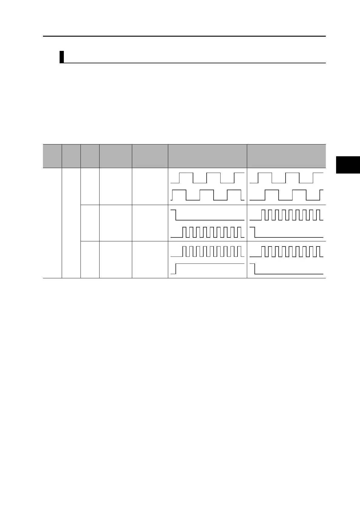
The functions of these signals depend on the settings of the Command Pulse Rotation Direction
Switching Selection (Pn006) and the Command Pulse Mode Selection (Pn007).
Note 1. If the Command Pulse Rotation Direction Switching Selection (Pn006) is set to 1, the rotation direction will be
reversed.
Pn005
Set
value
Pn006
Set
value
Pn007
Set
value
Command
pulse mode
Input pins Motor forward command Motor reverse command
10
0/2
90° phase
difference
signals
(quadruple
multiplier)
44: +FA
45: −FA
46: +FB
47: −FB
1
Reverse
pulse/
forward
pulse
44: +CW
45: −CW
46: +CCW
47: −CCW
3
Feed pulse/
direction
signal
44: +PULS
45: −PULS
46: +SIGN
47: −SIGN
L
H
 Loading...


