3-52
3-1 Servo Drive Specifications
OMNUC G5-SERIES AC SERVOMOTOR AND SERVO DRIVE USER'S MANUAL
3
Specifications
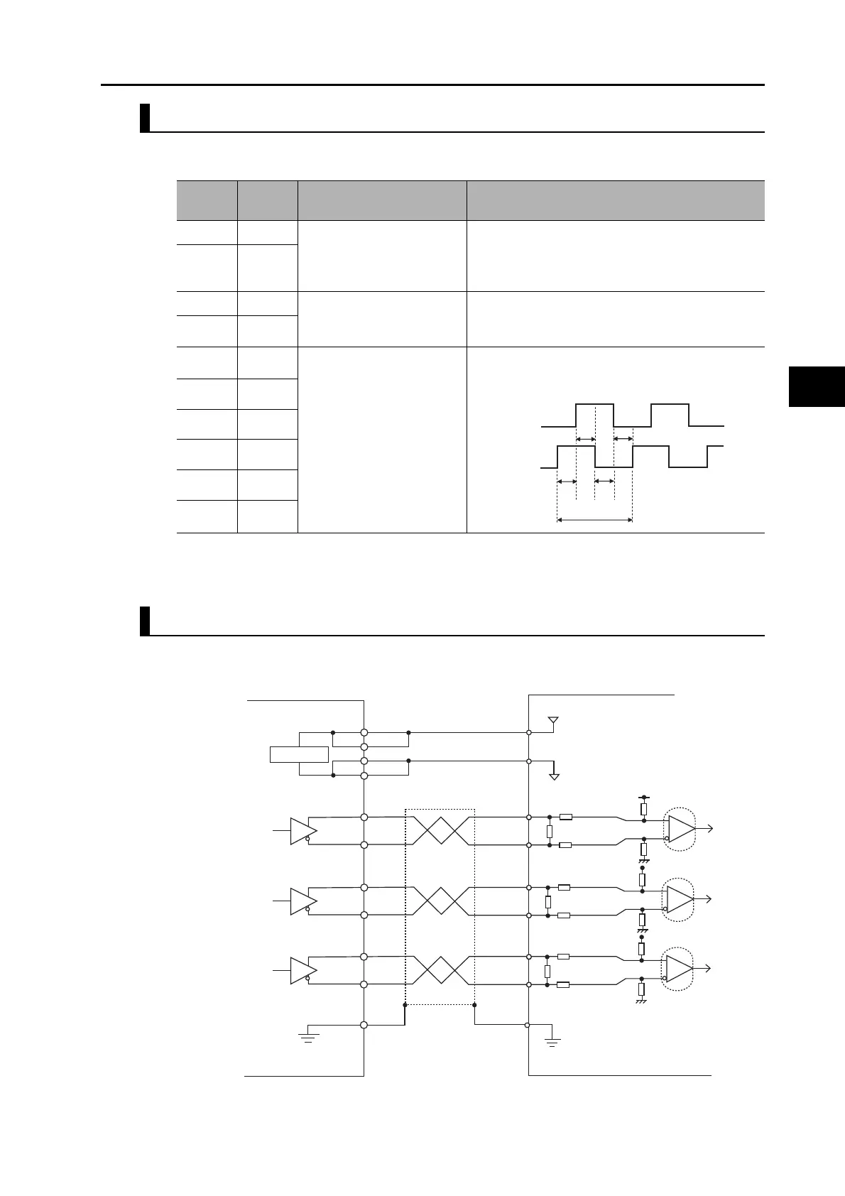
External Encoder Input Signals Table
External Encoder I/O (CN4)
* Connect external encoder signals to the serial interface (+EXS/−EXS) or 90° phase difference inputs
according to the encoder type.
Example of Connection with External Encoder
90° Phase Difference Output Type (Pn323 = 0)
Pin
number
Symbol Name Function and interface
1 E5V External encoder power
supply output
External encoder power supply: 5.2 VDC ± 5%, 250
mA max.
If the above capacity is exceeded, provide a
separate power supply.
2E0V
3 +EXS External encoder signal
serial interface
This is an external encoder serial bi-directional
signal.*(Conforming to EIA485)
Maximum response frequency: 400 Mpps
4 −EXS
5 +EXA
External encoder signal
90° phase difference input
(Phases A, B and Z)
This is an external encoder 90° phase input signal.*
Maximum response frequency: 4 Mpps (quadruple
multiplier)
6 −EXA
7 +EXB
8 −EXB
9 +EXZ
10 −EXZ
EXA
EXB
t1
t1
t1
t1
t2
t1>0.25 μs
t2>1.0 μs
Servo Drive side (CN4)
5.2 V
±
5% 250 mA max
+EXZ
−
EXZ
9
10
−
EXA
+EXA
GND
E5V
5 V
E0V
6
5
2
1
+EXB
−
EXB
7
8
FG
FG
+5 V
0 V
PA
/PA
PB
/PB
PC
/PC
FG
Power supply area
Phase Z
Phase A
Phase B
Shell
External encoder side
PULS
20 k
Ω
2 k
Ω
20 k
Ω
120
Ω
2 k
Ω
PULS
20 k
Ω
2 k
Ω
20 k
Ω
120
Ω
2 k
Ω
PULS
20 k
Ω
2 k
Ω
20 k
Ω
120
Ω
2 k
Ω
 Loading...


