3-113
3-4 Cable and Connector Specifications
OMNUC G5-SERIES AC SERVOMOTOR AND SERVO DRIVE USER'S MANUAL
3
Specifications
Wiring
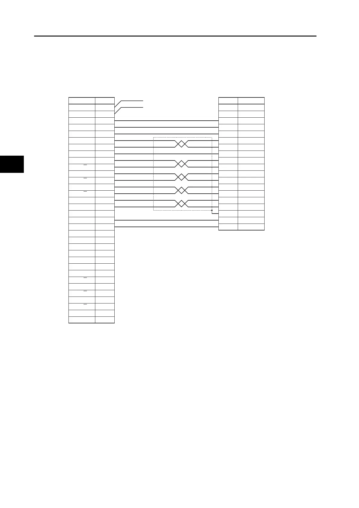
Cables for 1 axis
The symbols on the controller side are the DRVX and DRVY connector symbols. For the DRVZ
and DRVU connectors, X and Y are indicated as Z and U, respectively.
Terminals marked with asterisks are for absolute encoders.
Connect 24 VDC to the 2 lines (red and black) extending from the connector on the controller side.
(red: +24 V, black: -)
Symbol
Symbol
NumberNumber
Motion Control
Unit side
Servo Drive side
+24V
DCGND
XALM
XRUN
XALMRS
XSGND
XSOUT
X−GND
X−A
X−A
X−B
X−B
X−Z
X−Z
XOUT
XAGND
+F24V
1
2
3
4
5
8
9
10
11
12
13
14
15
16
17
18
19
FDC GND 20
21
22
23
26
27
28
29
30
31
32
33
34
35
36
YALM
YRUN
YALMRS
YSGND
YSOUT
Y−GND
Y−A
Y−A
Y−B
Y−B
Y−Z
Y−Z
YOUT
YAGND
37
29
31
13
20
25
21
22
49
48
23
24
14
15
Shell
7
36
/ALM
RUN
RESET
SENGND
SEN
ZGND
+A
−A
+B
−B
+Z
−Z
REF/TREF1/VLIM
AGND
FG
+24VIN
ALMCOM
*
*
AWG20 Red
AWG20 Black
White/Black (1)
Pink/Black (1)
Yellow/Black (1)
Gray/Black (1)
Gray/Red (1)
Orange/Black (2)
White/Red (1)
White/Black (1)
Yellow/Red (1)
Yellow/Black (1)
Pink/Red (1)
Pink/Black (1)
Orange/Red (1)
Orange/Black (1)
Orange/Black (1)
Gray/Black (1)
Connector plug model
10136-3000PE (Sumitomo 3M)
Connector case model
10336-52A0-008 (Sumitomo 3M)
Connector plug model
10150-3000PE
(Sumitomo 3M)
Connector case model
10350-52A0-008
(Sumitomo 3M)
Cable: AWG26
×
5P
+
AWG26
×
6C
 Loading...


