4-22
4-2 Wiring
OMNUC G5-SERIES AC SERVOMOTOR AND SERVO DRIVE USER'S MANUAL
4
System Design
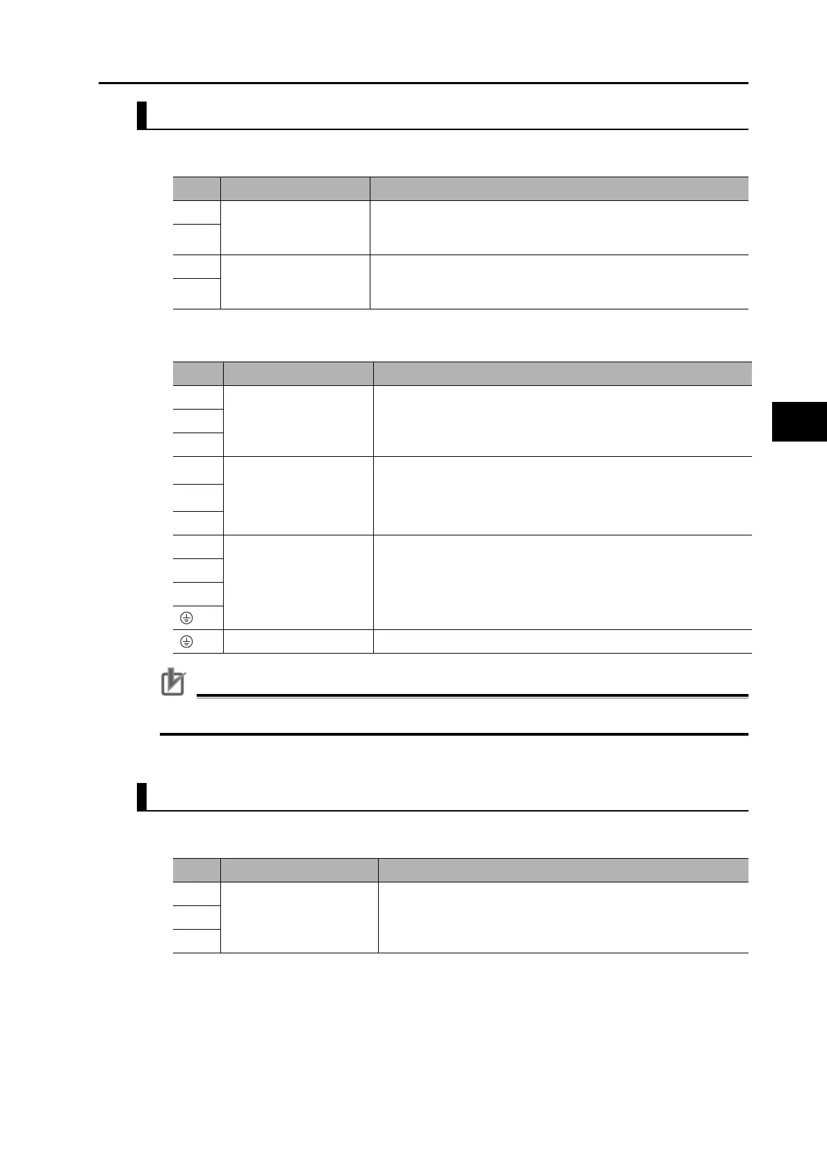
R88D-KT150H
Terminal Block Specifications, Top Terminal Block (TB1)
Terminal Block Specifications, Bottom Terminal Block (TB2)
Precautions for Correct Use
Never connect an External Regeneration Resistor between the B1 and N (NC) terminals
R88D-KT06F/-KT10F/-KT15F/-KT20F
Main Circuit Connector Specifications (CNA)
Symbol
Name Function
L1C
Control circuit power
supply input
R88D-KT@H: Single-phase 200 to 230 VAC (170 to 253 V) 50/60
Hz
280 to 325 VDC (238 to 357 VDC)
L2C
DB1 Dynamic brake
resistance control
terminals
These terminals are used to control the MC for externally connected
dynamic brake resistance. The output contact specifications are 1
A max. at 300 VAC/100 VDC max. Connect them if required.
DB2
Symbol
Name Function
L1
Main circuit power supply
input
R88D-KT@H (15 kW): 3-phase 200 to 230 VAC (170 to 253 V) 50/
60 Hz
280 to 325 VDC (238 to 357 VDC)
L2
L3
B1
External Regeneration
Resistor connection
terminals
Connect an External Regeneration Resistor between B1 and B2.
Terminal B1 is main circuit DC output (positive).
B2
N (NC)
U
Motor connection
terminals
These are the output terminals to the Servomotor.
Be sure to wire them correctly.
V
W
Frame ground This is the ground terminal. Ground to 100 Ω or less.
Symbol
Name Function
L1 Main circuit power supply
input
R88D-KT@F
(600 W to 2 kW) : 3-phase: 380 to 480 VAC (323 to 528 V) 50/60
Hz
L2
L3
 Loading...


