5-32
5-6 Fully-closed Control
OMNUC G5-SERIES AC SERVOMOTOR AND SERVO DRIVE USER'S MANUAL
5
Basic Control Mode
The corresponding external encoders for each output type are given in the following table.
*1. These are the directions in which the Servo Drive counts the pulses from a 90°phase difference output
type external encoder.
*2. These are the feedback speeds from the external encoder at which Servo Drive can respond.
Check the external encoder operation manual for its maximum output frequency.
For example, the maximum speed when an external encoder with a resolution of 0.01 μm is used for
the serial communication type is 0.01 μm × (400 × 10
6
) pps = 4.00 m/s.
An overspeed error protection is generated, however, if the motor shaft rotation speed exceeds the
maximum speed.
Precautions for Correct Use
For the external encoder connection direction, set the rotation direction so that count-up occurs
when the motor shaft is rotating counterclockwise, and count-down occurs when the motor shaft
is rotating clockwise. If the connection direction cannot be selected due to installation conditions,
etc., the count direction can be reversed using External Feedback Pulse Direction Switching
(Pn326).
Take note that if Pn000 = 1, the encoder count direction becomes opposite to the count direction
used for monitoring the total external encoder feedback pulses, etc.
If Pn000 = 0, the count direction matches the count direction for monitoring.
Even when the speed command is within the Drive’s speed command range, an acceleration error
will occur if the speed command exceeds the maximum speed of motor shaft rotation.
To confirm that the installation direction is correct, use the front-panel monitor or the CX-Drive
monitor function to check the counting direction of the total external encoder feedback pulses and
the total encoder feedback pulses. If the counting directions are the same, the connections are
correct.
Pn323
set
value
External encoder type
Corresponding external encoder
examples
Maximum input
frequency *
2
0
90° phase difference
output type
*1
90° phase difference output type external
encoder
0 to 4 Mpps
(After × 4)
1
Incremental encoder with
serial communications
Sony Manufacturing Systems Corporation
SR75, SR85
0 to 400 Mpps
2 Reserved (Do not use this setting.)
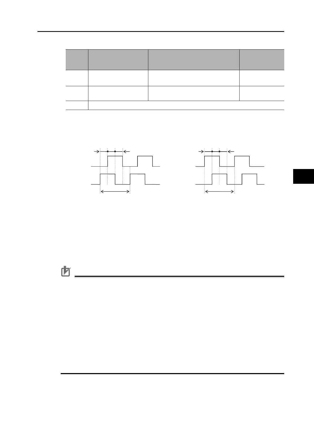
Count-down direction Count-up direction
EXB is 90° ahead of EXA.
t1>0.25 μs
t2>1.0 μs
t1
t2
EXA
EXB
EXB is 90° behind EXA.
t1>0.25 μs
t2>1.0 μs
t1
t2
EXA
EXB
 Loading...


