6-26
6-7 Gain Switching Function
OMNUC G5-SERIES AC SERVOMOTOR AND SERVO DRIVE USER'S MANUAL
6
Applied Functions
Diagrams of Gain Switching Setting
Switching between Gain 1 (Pn100 to Pn104) and Gain 2 (Pn105 to Pn109) occurs at the
following times. Take note that, in the case of position loop gains, switching occurs based on
the setting of Pn119.
For the details of each gain, refer to "Chapter 8, Parameter Details".
The details of the gain switching setting vary depending on the control mode used. For the
details of settings available in each mode, refer to "Gain Switching Setting for Each Control
Mode" (P.6-30).
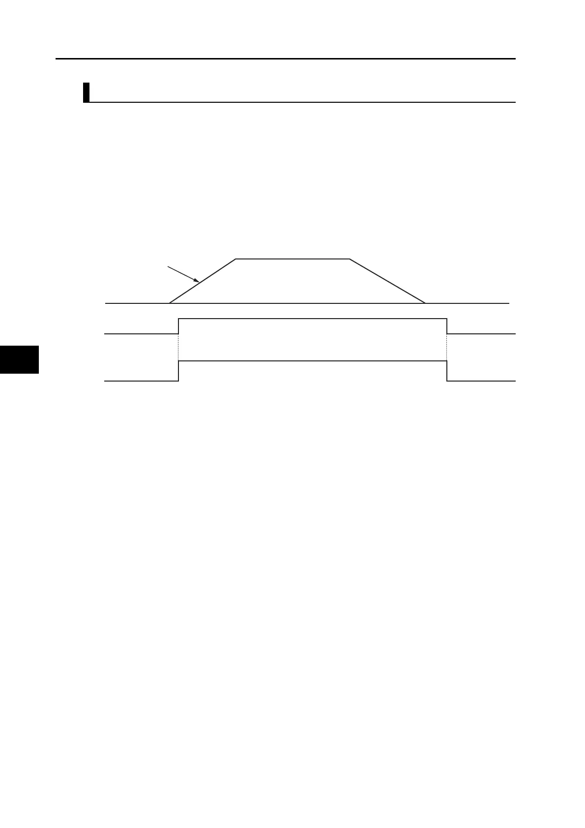
Gain Switching Mode = 2: Gain Switching (GSEL)
The gain is switched instantly when a gain switching command is issued by external input.
Gain 1
GSEL
Gain 1
Gain 2
Gain switching instruction
Position command
 Loading...


