6-38
6-9 Sequence I/O Signal
OMNUC G5-SERIES AC SERVOMOTOR AND SERVO DRIVE USER'S MANUAL
6
Applied Functions
Precautions for Correct Use
Do not use any values other than the settings listed.
If you allocate the same function to multiple input signals, interface input duplicate allocation error
1 (Alarm 33.0) or interface input duplicate allocation error 2 (Alarm 33.1) will occur.
You can allocate error counter reset input (ECRST) to Input Signal Selection 7 (Pn406) only. If
you allocate it to anything other than that, a counter reset allocation error (Alarm 33.6) will occur.
You can allocate pulse prohibition input (IPG) to Input Signal Selection 10 (Pn409) only. If you allocate
it to anything other than that, a command pulse prohibition input allocation error (Alarm 33.7) will
occur.
If you are using the control mode switching input (TVSEL), you must set it for all control mode. If
you do not set it for all control mode, interface input function number error 1 (Alarm 33.2) or
interface input function number error 2 (Alarm 33.3) will occur.
If you set Zero Speed Designation Selection (Pn315) to 2 or 3, you must always allocate zero
speed designation input (VZERO) in speed control for the same pin where zero speed designation
input (VZERO) is allocated for speed control. In addition, specify the same settings for the logic.
Be sure to allocate the functions that are used by multiple control mode (such as operation command and
alarm reset input) to the same pin, and do the same for the logic. If this is not set correctly, interface input
duplicate allocation error 1 (Alarm 33.0) or interface input duplicate allocation error 2 (Alarm 33.1) will
occur.
You must always allocate the operation command (RUN). Servo cannot be turned ON if it is not
allocated.
Output Signals
You can allocate output signal functions to the output pins for the control I/O connector (CN1).
If a G-series Servo Drive is being replaced with a G5-series Servo Drive, use the G5-series
Servo Drive with the default settings.
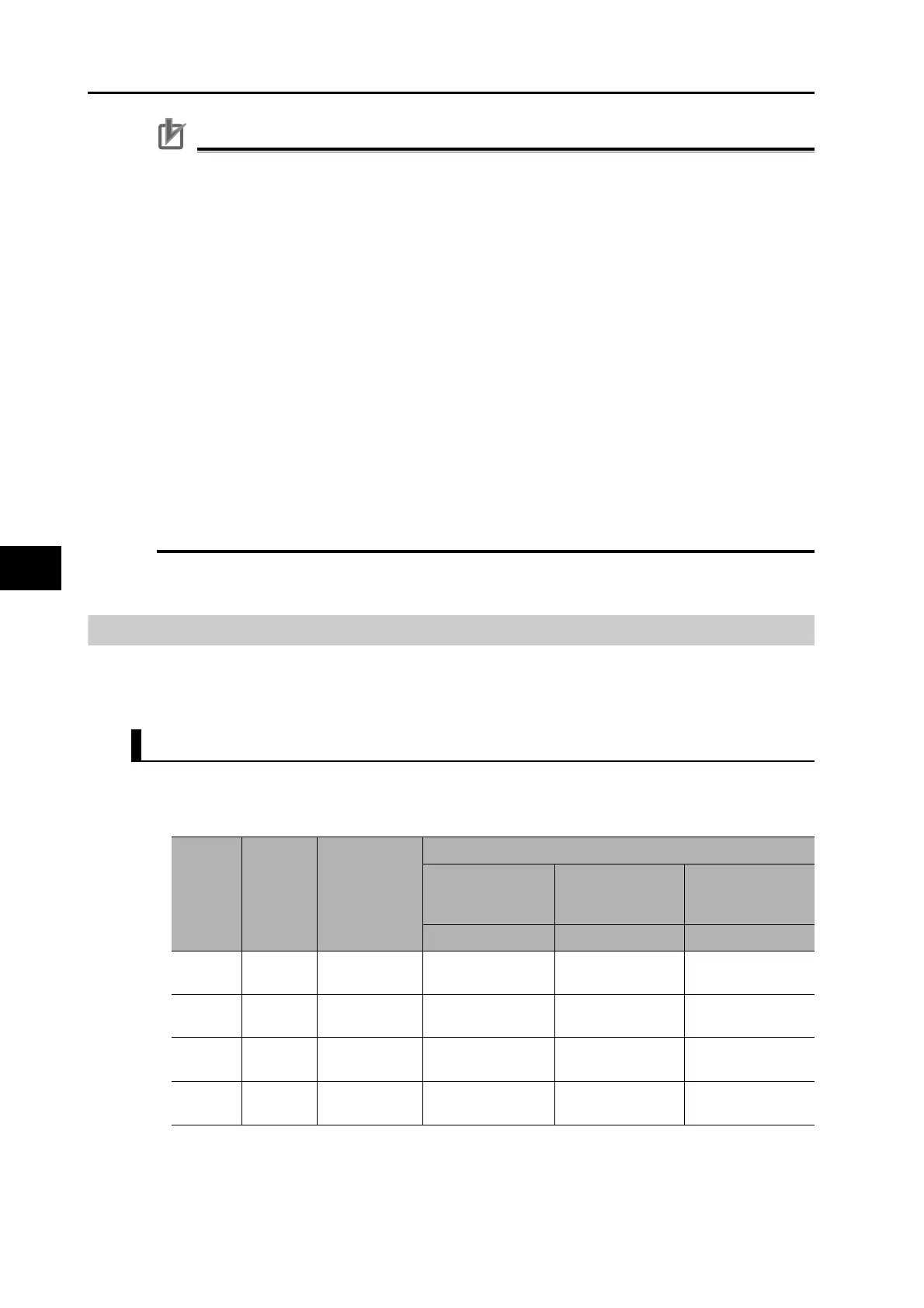
Output Signal Default Setting
The allocations of the default output signals are as follows. Refer to "Output Signal Allocation
Method" when you change the allocation to use.
*1 Alarm output signal allocations cannot be changed.
Applicable
parameters
Output
Signals
Default set
value
Default setting state
Position control
or fully-closed
control
Speed control Torque control
Signal name Signal name Signal name
Pn410
SO1
output
00030303h
(197379)
BKIR BKIR BKIR
Pn411
SO2
output
00020202h
(131586)
READY READY READY
Pn412
SO3
output
*1 ALM ALM ALM
Pn413
SO4
output
00050504h
(328964)
INP TGON TGON
 Loading...


