6-40
6-9 Sequence I/O Signal
OMNUC G5-SERIES AC SERVOMOTOR AND SERVO DRIVE USER'S MANUAL
6
Applied Functions
Function Number Table
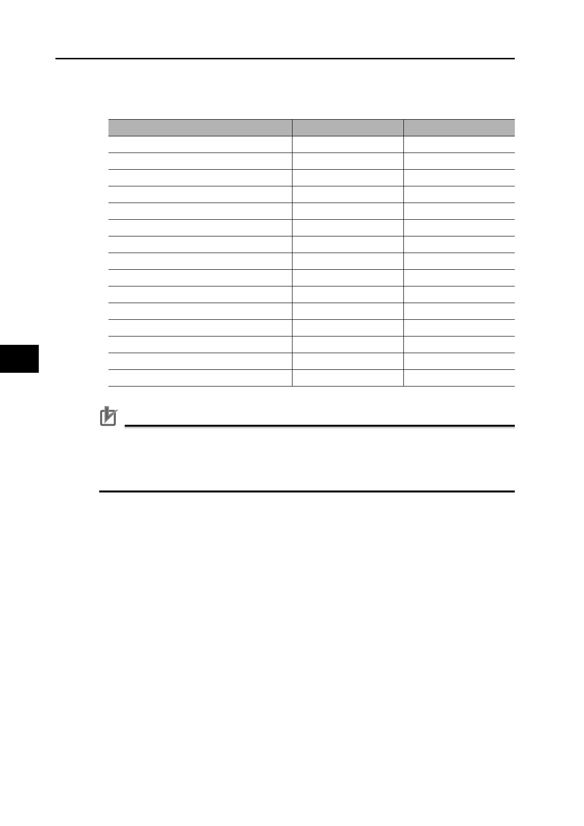
The set values to be used for allocations are as follows:
Precautions for Correct Use
Do not use any values other than the settings listed.
You can allocate the same function to more than one output signal.
You cannot change the output signal logic. When the function is disabled (OFF), signal input is
open with COM−, and when the function is enabled (ON), signal input is shorted with COM−.
Signal name Symbol Set value
Disabled − 00h
Servo ready completed output READY 02h
Brake interlock output BKIR 03h
Positioning completion output INP 04h
Motor rotation speed detection output TGON 05h
Torque limiting signal TLC 06h
Zero speed detection output ZSP 07h
Speed conformity output VCMP 08h
Warning output 1 WARN1 09h
Warning output 2 WARN2 0Ah
Position command status output P-CMD 0Bh
Positioning completion output 2 INP2 0Ch
Output during speed limit V-LIMIT 0Dh
Alarm attribute output ALM-ATB 0Eh
Speed command status output V-CMD 0Fh
 Loading...


