8-18
8-2 Gain Parameters
OMNUC G5-SERIES AC SERVOMOTOR AND SERVO DRIVE USER'S MANUAL
8
Parameter Details
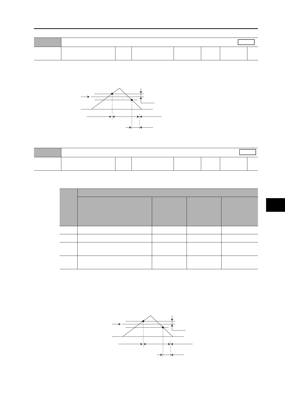
Set the hysteresis width above and below the judgment level set in the Gain Switching Level in Speed
Control (Pn122). The unit depends on the setting of the Switching Mode in Speed Control (Pn120).
The following shows the definitions for the Gain Switching Delay Time in Speed Control (Pn121), Gain
Switching Level in Speed Control (Pn122), and Gain Switching Hysteresis in Speed Control (Pn123).
The settings for the Gain Switching Level in Speed Control (Pn122) and the Gain Switching
Hysteresis in Speed Control (Pn123) are enabled absolute values (positive/negative).
Explanation of Settings
Select the switching condition between gain 1 and gain 2 when the Gain Switching Input Operating
Mode Selection (Pn114) is set to 1.
The gain is always gain 1 regardless of the gain input if the switching input is not assigned when
Pn124=2.
*1. The Gain Switching Delay Time in Torque Control (Pn125) becomes effective the gain is switched
from 2 to 1.
*2. The Gain Switching Hysteresis in Torque Control (Pn127) is defined as shown in the following figure.
*3. The variation means the change amount in a millisecond (ms).
E.g. The set value is 200 when the condition is a 10% change in torque in 1 millisecond.
Pn123
Gain Switching Hysteresis in Speed Control
Setting
range
0 to 20,000 Unit −
Default
setting
0
Power OFF
and ON
−
Speed
Pn122
0
Pn123
Pn121
Gain 1
Gain 2
Gain 1
Pn124
Switching Mode in Torque Control
Setting
range
0 to 3 Unit −
Default
setting
0
Power OFF
and ON
−
Torque
Set
value
Explanation
Gain switching conditions
Gain
Switching
Delay Time in
Torque Control
(Pn125)
*1
Gain
Switching
Level in
Torque Control
(Pn126)
Gain Switching
Hysteresis in
Torque Control
(Pn127)
*2
0 Always Gain 1 (Pn100 to Pn104) −−−
1 Always Gain 2 (Pn105 to Pn109) −−−
2
Switching using gain switching input
(GSEL) for CN1 pin 27
−−−
3
Torque command variation (Refer to
Figure A)
√
√
*3
(0.05%)
√
*3
(0.05%)
Pn126
0
Pn127
Pn125
Gain 1
Gain 2
Gain 1
 Loading...


