8-58
8-6 Extended Parameters
OMNUC G5-SERIES AC SERVOMOTOR AND SERVO DRIVE USER'S MANUAL
8
Parameter Details
Explanation of Set Values
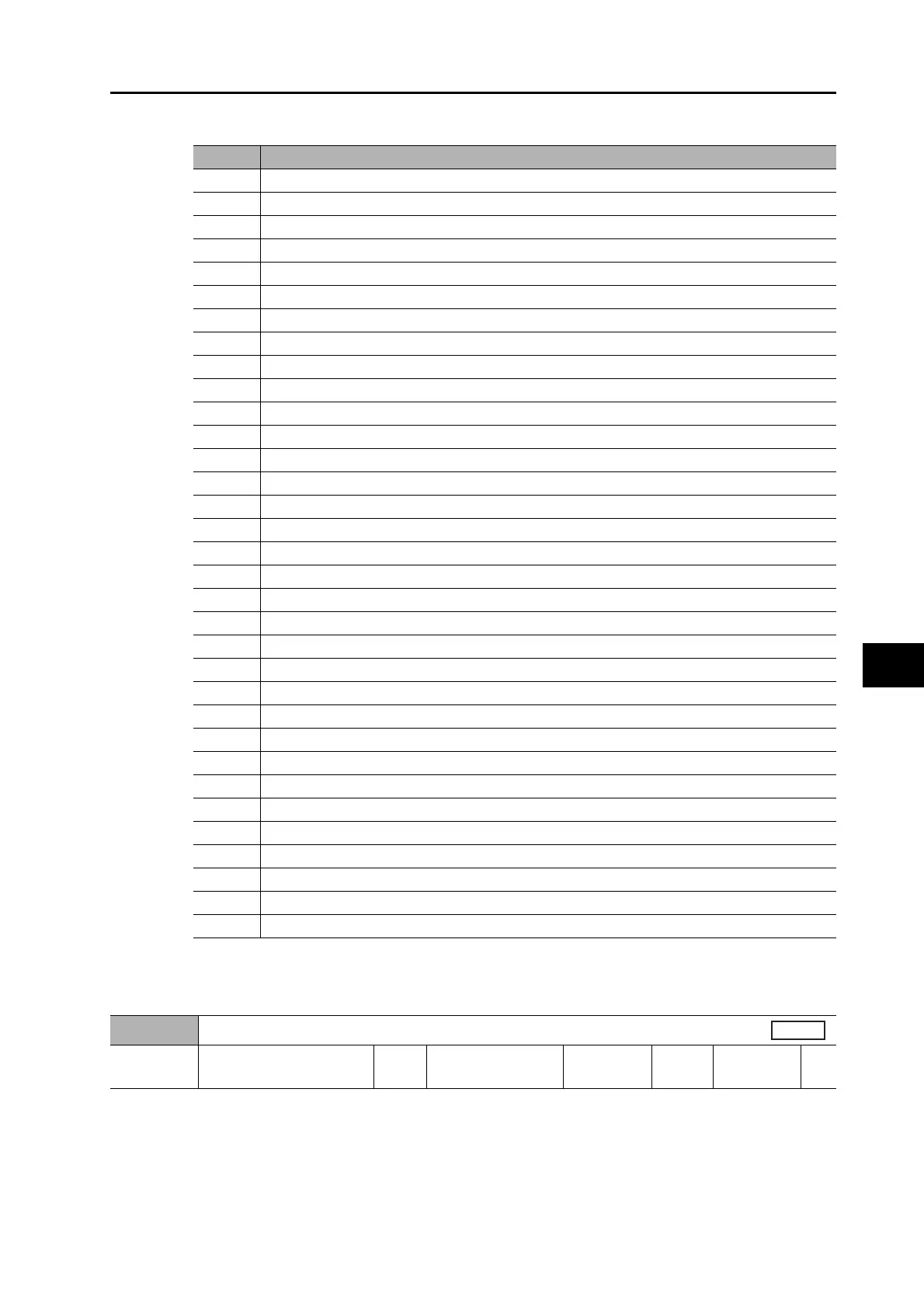
Select the data to be displayed on the 7-segment LED on the front panel after the power supply
is turned ON.
For information on the display, refer to "9-4 Setting the Mode" (P.9-7).
Set the axis number for USB communications. Normally, do not change the set value.
Set value
Description
0 Position command error
1 Motor speed
2 Position command speed
3 Speed control command
4 Torque command
5 Total encoder pulses
6 Total command pulses
8 Total external encoder feedback pulses
9 Control mode
10 I/O signal status
11 Analog input value
12 Alarm factor, history
13 Warning number
14 Regeneration resistance load ratio
15 Overload load ratio
16 Inertia ratio
17 Reason for no rotation
18 Display of the number of I/O signal changes
20 Absolute encoder data
21 Absolute external encoder position
22 Monitor for the number of encoder communications errors
23 Display of axis numbers for communication
24 Position error (encoder unit)
25 External encoder error (external encoder unit)
26 Hybrid error
27 P-N voltage
28 Soft version
29 Drive serial number
30 Motor serial number
31 Accumulative operation time
32 Automatic motor recognition function
33 Temperature information
35 Safety status monitor
Pn531
Axis Number
Setting
range
0 to 127 Unit −
Default
setting
1
Power OFF
and ON
Yes
 Loading...


