10-5
10-2 Realtime Autotuning
OMNUC G5-SERIES AC SERVOMOTOR AND SERVO DRIVE USER'S MANUAL
10
Adjustment Functions
Precautions for Correct Use
Unusual noise or vibration may occur until the load inertia is estimated or the adaptive filter
stabilizes after startup, immediately after the first servo ON, or when the Realtime Autotuning
Machine Rigidity Selection (Pn003) is increased. This is not an error if it disappears right away. If
the unusual noise or vibration, however, continues for 3 or more reciprocating operations, take the
following measures in any order you can.
Write the parameters used during normal operation to the EEPROM.
Lower the Realtime Autotuning Machine Rigidity Selection (Pn003).
Manually set the notch filter.
Once unusual noise or vibration occurs, Inertia Ratio (Pn004), Torque Command Value Offset
(Pn607), Forward Direction Torque Offset (Pn608), and Reverse Direction Torque Offset (Pn609)
may have changed to an extreme value. In this case, also take the measures described above.
Out of the results of realtime autotuning, the Inertia Ratio (Pn004), Torque Command Value Offset
(Pn607), Forward Direction Torque Offset (Pn608) and Reverse Direction Torque Offset (Pn609)
are automatically saved to the EEPROM every 30 minutes. Realtime autotuning will use this
saved data as the default setting when the power supply is turned OFF and turned ON again.
The parameter will automatically be set based on the Realtime Autotuning Machine Rigidity
Setting (Pn003) if realtime autotuning is enabled.
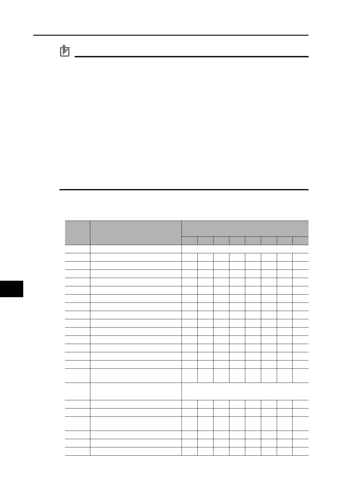
Realtime Autotuning (RTAT) Parameter Table
Parameter
number
Parameter name
AT Machine Rigidity Setting (Pn003)
0 1 2 3 4 5 6 7
Pn004 Inertia Ratio Estimated load inertia ratio
Pn100 Position Loop Gain 20 25 30 40 45 55 75 95
Pn101 Speed Loop Gain 15 20 25 30 35 45 60 75
Pn102 Speed Loop Integral Time Constant 3700 2800 2200 1900 1600 1200 900 700
Pn103 Speed Feedback Filter Time Constant 0 0000000
Pn104 Torque Command Filter Time Constant 1
*1
1500 1100 900 800 600 500 400 300
Pn105 Position Loop Gain 2 25 30 40 45 55 70 95 120
Pn106 Speed Loop Gain 2 15 20 25 30 35 45 60 75
Pn107 Speed Loop Integral Time Constant 2
*2
10000 10000 10000 10000 10000 10000 10000 10000
Pn108 Speed Feedback Filter Time Constant 2 0 0000000
Pn109 Torque Command Filter Time Constant 2
*1
1500 1100 900 800 600 500 400 300
Pn110 Speed Feed-forward Amount 300 300 300 300 300 300 300 300
Pn111
Speed Feed-forward Command Filter
50 50 50 50 50 50 50 50
Pn112 Torque Feed-forward Amount 0 0000000
Pn113 Torque Feed-forward Command Filter 0 0000000
Pn114
Gain Switching Input Operating Mode
Selection
11111111
Pn115 Switching Mode in Position Control
Gain Switching Enable Mode: 10
Gain Switching Disable Mode: 0
Pn116
Gain Switching Delay Time in Position Control
30 30 30 30 30 30 30 30
Pn117 Gain Switching Level in Position Control 50 50 50 50 50 50 50 50
Pn118
Gain Switching Hysteresis in Position
Control
33 33 33 33 33 33 33 33
Pn119 Position Gain Switching Time 33 33 33 33 33 33 33 33
Pn120 Switching Mode in Speed Control 0 0000000
Pn121
Gain Switching Delay Time in Speed Control
00000000
 Loading...


