10-9
10-2 Realtime Autotuning
OMNUC G5-SERIES AC SERVOMOTOR AND SERVO DRIVE USER'S MANUAL
10
Adjustment Functions
*1. This is limited to a minimum value of 10 if a 17-bit absolute encoder is used.
*2 If realtime autotuning is performed in vertical axis mode or friction compensation and vertical axis
mode, the value will be 9999 until load characteristic estimation (estimation of the inertia ratio, torque
command value offset, and forward/reverse direction torque offset) is completed. The value will
change to 10000 after the load characteristic estimation is completed.
The parameters Pn103, Pn108, Pn110 to Pn127, Pn605, Pn606, Pn610, Pn611, Pn613, Pn623
and Pn624 are set to fixed values.
Pn103
Speed Feedback Filter Time Constant
00000000
Pn104 Torque Command Filter Time Constant 1
*1
98776655
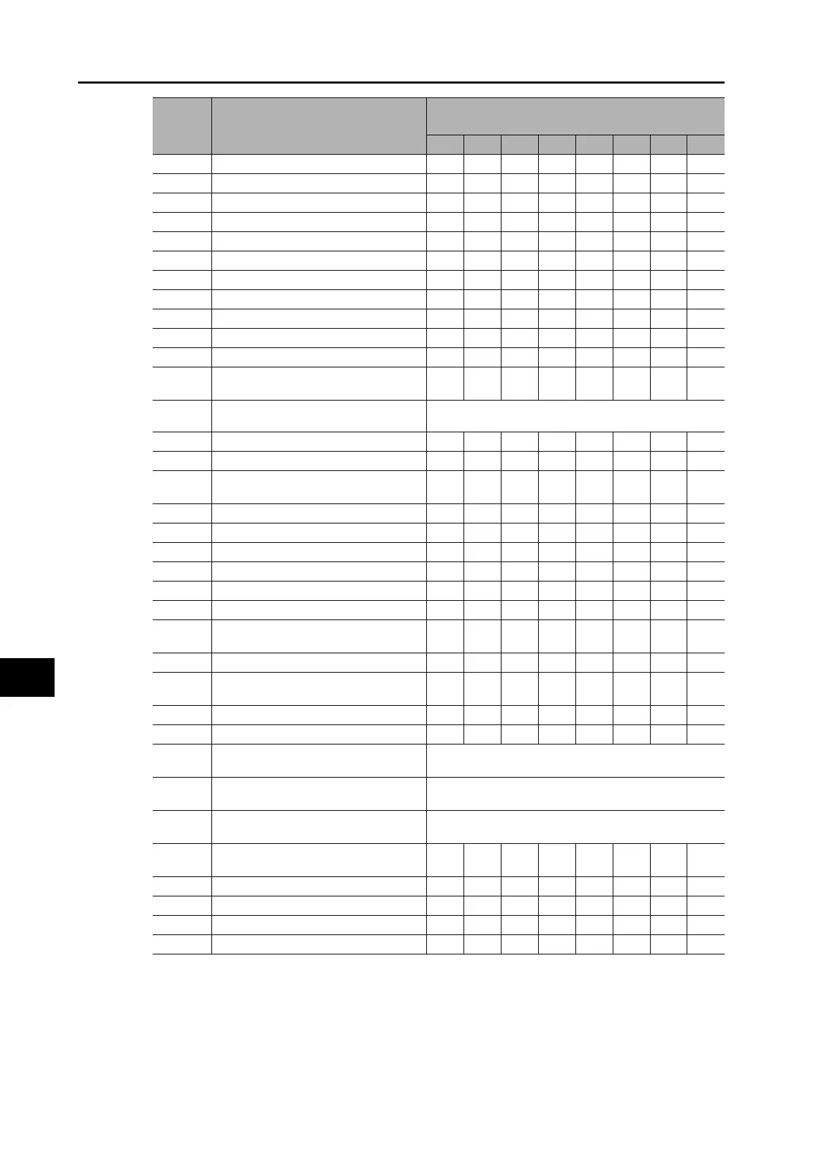
Pn105 Position Loop Gain 2 5240 5900 6500 7100 7700 8400 9400 10500
Pn106 Speed Loop Gain 2 2500 2800 3100 3400 3700 4000 4500 5000
Pn107 Speed Loop Integral Time Constant 2
*2
10000 10000 10000 10000 10000 10000 10000 10000
Pn108 Speed Feedback Filter Time Constant 2 0 0000000
Pn109 Torque Command Filter Time Constant 2
*1
98776655
Pn110 Speed Feed-forward Amount 300 300 300 300 300 300 300 300
Pn111
Speed Feed-forward Command Filter
50 50 50 50 50 50 50 50
Pn112 Torque Feed-forward Amount 0 0000000
Pn113 Torque Feed-forward Command Filter 0 0000000
Pn114
Gain Switching Input Operating Mode
Selection
11111111
Pn115 Switching Mode in Position Control
Gain Switching Enable Mode: 10
GAIN Switching Disable Mode: 0
Pn116
Gain Switching Delay Time in Position Control
30 30 30 30 30 30 30 30
Pn117 Gain Switching Level in Position Control 50 50 50 50 50 50 50 50
Pn118
Gain Switching Hysteresis in Position
Control
33 33 33 33 33 33 33 33
Pn119 Position Gain Switching Time 33 33 33 33 33 33 33 33
Pn120 Switching Mode in Speed Control 0 0000000
Pn121
Gain Switching Delay Time in Speed Control
00000000
Pn122 Gain Switching Level in Speed Control 0 0000000
Pn123 Gain Switching Hysteresis in Speed Control 0 0000000
Pn124 Switching Mode in Torque Control 0 0000000
Pn125
Gain Switching Delay Time in Torque
Control
00000000
Pn126
Gain Switching Level in Torque Control
00000000
Pn127
Gain Switching Hysteresis in Torque
Control
00000000
Pn605 Gain 3 Effective Time 0 0000000
Pn606 Gain 3 Ratio Setting 100 100 100 100 100 100 100 100
Pn607 Torque Command Value Offset
If Pn002 = 3 or 4, this is the estimated offset for the torque
command.
Pn608 Forward Direction Torque Offset
If Pn002 = 3 or 4, this is the estimated offset for the torque
command.
Pn609 Reverse Direction Torque Offset
If Pn002 = 3 or 4, this is the estimated offset for the torque
command.
Pn610.0,
Pn610.3
Function Expansion Setting 00000000
Pn611 Electric Current Response Setting 100 100 100 100 100 100 100 100
Pn613 Inertia Ratio 2 0 0000000
Pn623 Disturbance Torque Compensation Gain 0 0000000
Pn624 Disturbance Observer Filter Setting 0 0000000
Parameter
number
Parameter name
AT Machine Rigidity Setting (Pn003)
24 25 26 27 28 29 30 31
 Loading...


