12.2 b: APPLICATION
542 SIEPYEUOQ2A01A AC Drive Q2A Technical Manual
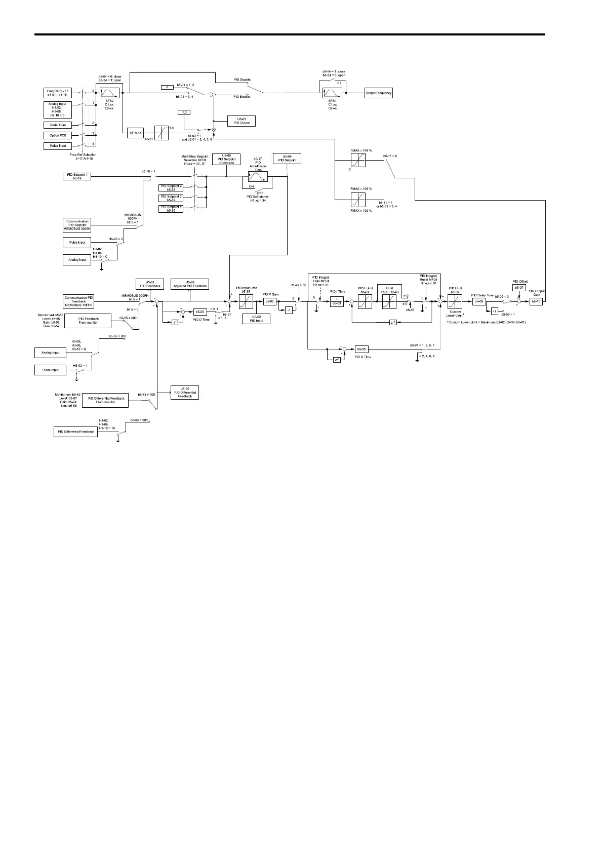
■ PID Control Block Diagram
Figure 12.29 PID Control Block Diagram
■ PID Feedback Loss Detection
The PID feedback loss detection function detects broken sensors and defective wiring between the drive and
sensors.
Use the PID feedback loss detection function when you use PID control. If the feedback signal is too low, the
motor can suddenly accelerate to the maximum output frequency. This function prevents such risks to the load.
The drive uses two methods to detect feedback loss:
• PID Feedback Loss [FbL]
Set these parameters for the PID feedback loss detection function.
The drive detects feedback loss when the feedback value is less than the value in b5-13 for longer than the time
in b5-14.
– b5-12 [Fdback Loss Select Mode]
– b5-13 [Fdback Loss Lvl]
– b5-14 [Fdback Loss Time]
• Excessive PID Feedback [FbH]
Set these parameters to set how the drive detects a feedback level that is too high.
The drive detects too much PID feedback when the feedback value is more than the value in b5-36 for longer
than the time in b5-37.
– b5-12 [Fdback Loss Select Mode]
– b5-36 [PID HiHi Limit Level]
– b5-37 [PID HiHi Time]
Figure 12.30 shows the operation principle when the feedback value is too low, and the drive detects feedback
loss. The operation is the same when the drive detects too much feedback.

 Loading...


