12.7 H: TERMINALS
708 SIEPYEUOQ2A01A AC Drive Q2A Technical Manual
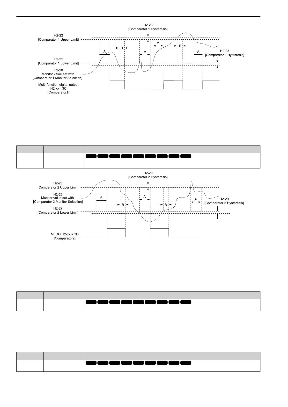
A - H2-24
[Compare1 On-Delay Time]
B - H2-25
[Compare1 Off-Delay Time]
Figure 12.96 Comparator 1 Output Time Chart
Note:
The drive compares the monitors set with H2-20 as absolute values.
■ 3D: Comparator 2
Setting Function Description
3D Comparator 2
The monitor value set with H2-26 [Compare2 Mon.Selection] is on while in range of the time set with H2-30 [Compare2 On-
Delay Time] and the values of H2-27 [Compare2 Low Limit] and H2-28 [Compare2 Up Limit] are in range.
A - H2-30
[Compare2 On-Delay Time]
B - H2-31
[Compare2 Off-Delay Time]
Figure 12.97 Comparator 2 Output Time Chart
Note:
The drive compares the monitors set with H2-26 as absolute values.
■ 3E: PID Fbk Low
Setting Function Description
3E PID Fbk Low
The activates when the drive detects FbL [PID Feedback Loss].
The drive detects FbL [PID Feedback Loss] when the PID feedback value < b5-13 [Fdback Loss Lvl] for longer
than the time set in b5-14 [Fdback Loss Time].
Note:
Refer to “PID Feedback Loss Detection” for more information.
■ 3F: PID Fbk High
Setting Function Description
3F PID Fbk High
The terminal activates when the drive detects FbH [Excessive PID Feedback].
 Loading...


