Electrical Installation
3
3.5 Control Circuit Wiring
SIEPYEUOQ2A01A AC Drive Q2A Technical Manual 87
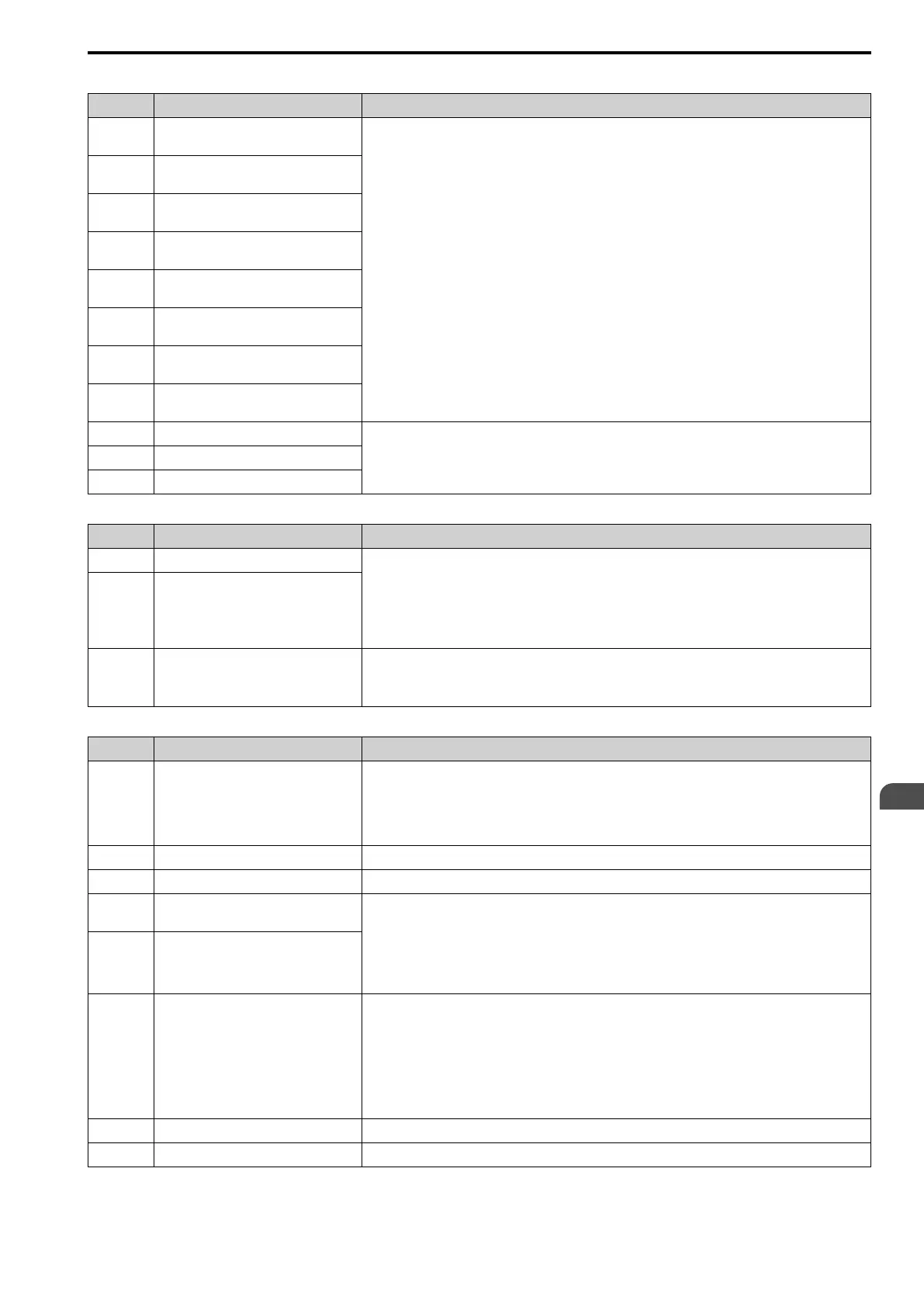
Table 3.4 Digital Inputs
Terminal Name (Default) Function (Signal Level)
DI1
MFDI selection 1
(ON: Forward run OFF: Stop)
• Photocoupler
• 24 V, 6 mA
Note:
Install the wire jumpers between terminals DIC-D24V and DIC-D0V to set the MFDI power supply (sinking/
sourcing mode or internal/external power supply).
• Sinking Mode: Install a jumper between terminals DIC and D24V.
NOTICE: Do not close the circuit between terminals DIC and D0V in Sinking
Mode. Failure to obey will cause damage to the drive.
• Sourcing Mode: Install a jumper between terminals DIC and D0V.
NOTICE: Do not close the circuit between terminals DIC and D24V in Source
Mode. Failure to obey will cause damage to the drive.
• External power supply: No jumper necessary between terminals DIC-D0Vand terminals DIC-D24V.
DI2
MFDI selection 2
(ON: Reverse run OFF: Stop)
DI3
MFDI selection 3
(External fault (N.O.))
DI4
MFDI selection 4
(Fault reset)
DI5
MFDI selection 5
(Multi-step speed reference 1)
DI6
MFDI selection 6
(Multi-step speed reference 2)
DI7
MFDI selection 7
(Jog command)
DI8
MFDI selection 8
(Baseblock command (N.O.))
D0V MFDI power supply 0 V
MFDI power supply, 24 V (maximum 150 mA)
NOTICE: Do not close the circuit between terminals D24V and D0V. Failure to
obey will cause damage to the drive.
DIC MFDI selection common
D24V MFDI power supply +24 Vdc
Table 3.5 Safe Disable Input
Terminal Name (Default) Function (Signal Level)
H1 Safe Disable input 1
Remove the jumper between terminals H1-HC and H2-HC to use the Safe Disable input.
• 24 V, 6 mA
• ON: Normal operation
• OFF: Coasting motor
• Internal impedance 4.7 kΩ
• OFF Minimum OFF time of 2 ms.
H2 Safe Disable input 2
HC Safe Disable function common
Safe Disable function common
NOTICE: Do not close the circuit between terminals HC and D0V. Failure to obey
will cause damage to the drive.
Table 3.6 Master Frequency Reference
Terminal Name (Default) Function (Signal Level)
PI
Master frequency reference pulse train input
(Master frequency reference)
• Response frequency: 0 Hz to 32 kHz
• H level duty: 30% to 70%
• H level voltage: 3.5 V to 13.2 V
• L level voltage: 0.0 V to 0.8 V
• Input impedance: 3 kΩ
+10V Power supply for frequency setting 10.5 V (allowable current 20 mA maximum)
-10V Power supply for frequency setting -10.5 V (allowable current 20 mA maximum)
AI1
MFAI1
(Master frequency reference)
Voltage input or current input
Select terminal AI1 with DIP switch S1-1 and H3-01 [AI1 Signal Level Select].
Select terminal AI2 with DIP switch S1-2 and H3-09 [AI2 Signal Level Select].
• -10 V to +10 V/-100% to +100% (input impedance: 20 kΩ)
• 0 V to 10 V/100% (input impedance: 20 kΩ)
• 4 mA to 20 mA/100%, 0 mA to 20 mA/100% (input impedance: 250 Ω)
AI2
MFAI2
(Combined to terminal A1)
AI3
MFAI3/PTC input
(Auxiliary frequency reference)
• Voltage input or current input
Select with DIP switch S1-3 and H3-05 [AI3 Signal Level Select].
– -10 V to +10 V/-100% to +100% (input impedance: 20 kΩ)
– 0 V to 10 V/100% (input impedance: 20 kΩ)
– 4 mA to 20 mA/100%, 0 mA to 20 mA/100% (input impedance: 250 Ω)
• PTC input (Motor Overheat Protection)
Set DIP switch S4 to “PTC” and set DIP switch S1-3 to “V” to set terminal AI3 for PTC input.
A0V Frequency reference common 0 V
GND Connecting shielded cable -

 Loading...


