13
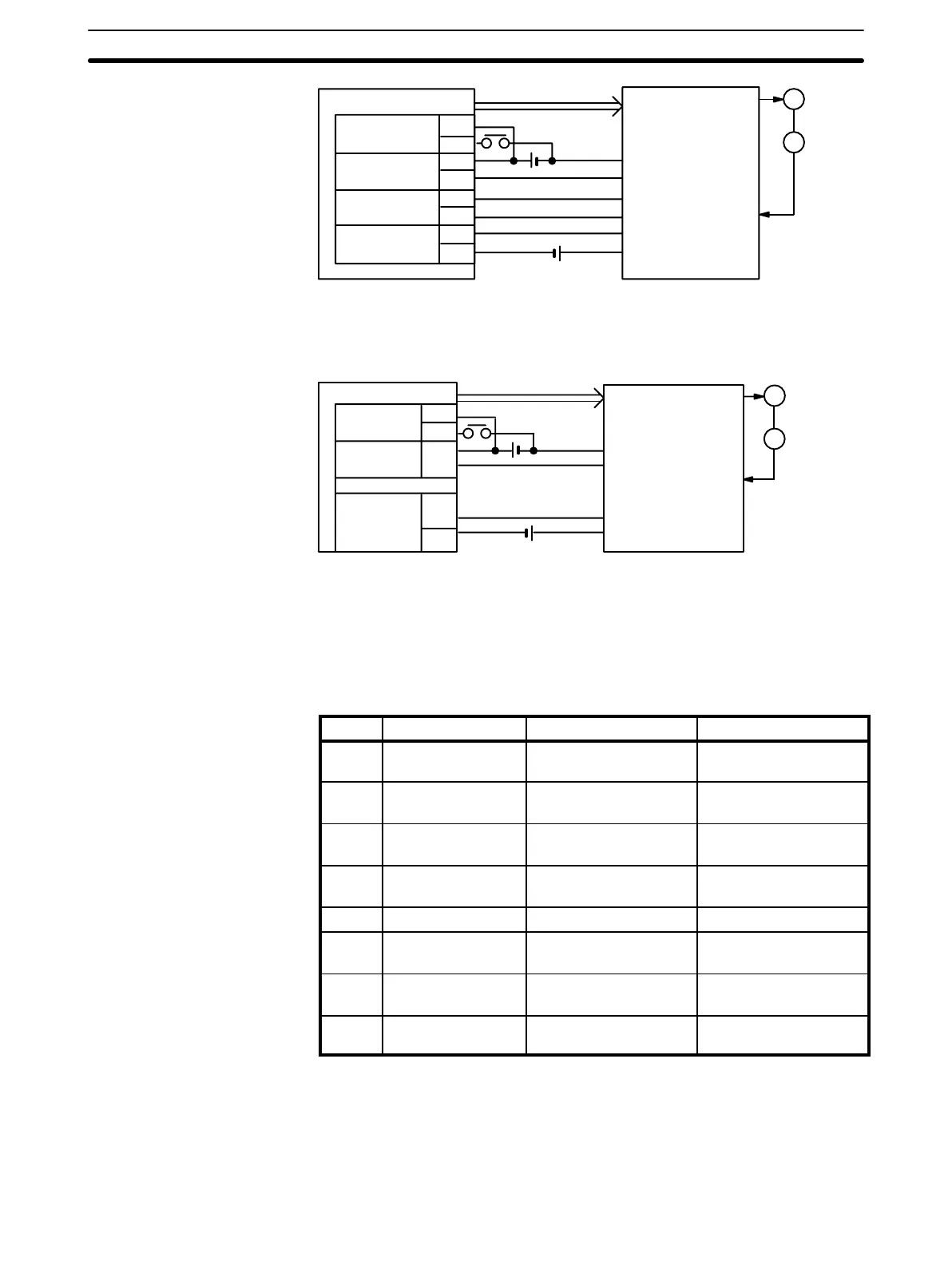
Origin
proximity
NC112
Positioning
completed
Origin line
driver
Deviation
counter reset
A10
B10
A9
B9
A8
B8
Pulse
24 VDC
5 VDC
Servomotor driver
Driver completed
signal output
Z-phase output
Deviation counter
reset input
M
E
A6
B6
+
–
This mode is used when a servomotor driver having an origin adjustment sig-
nal (such as OMRON Model R88D) is used.
Origin
proximity
Origin adjustment
signal input
A10
B10
A9
B9
A7
B7
NC112
Positioning
completed
Origin
adjustment
command
Pulse
24 VDC
5 VDC
Servomotor driver
Driver completed
signal output
M
E
Note The above wiring diagrams for modes 1, 2, and 3 are applicable when an
OMRON R88D Servomotor Driver is used.
Adjust the servomotor driver so that its positioning complete signal turns OFF
while the motor is operating and ON when the motor stops.
These pins must be set before the Unit is mounted.
Pin no. Name ON OFF
1 Output pulse
selector
Nondirectional pulse and
direction signal outputs.
Separate CW and CCW
pulse outputs
2 Origin search
direction
CCW CW
3 Origin proximity
present/absent
Present Absent
4 Origin proximity
signal type
NO input NC input
5 Origin signal type NO input NC input
6 External interrupt
signal type
Fixed via pin #7 Determined by IR word
n, bit 06
7 External interrupt
signal definition
CHANGE SPEED STOP
8 Origin proximity
reverse
Present Absent
Note Setting origin proximity to absent is possible in mode 0, but in modes 1, 2, or
3, even if origin proximity is set to absent, operation is performed with origin
proximity present.
When this pin is set to the ON position, the Position Control Unit outputs non-
directional pulses and a direction signal; when it is set to the OFF position,
Mode 3
Back Panel DIP Switch
Pin 1: Output Pulse
Selector
Switch Settings Section 2–1