11-15
11 High-speed Counters
CP2E CPU Unit Software User’s Manual(W614)
11-3 High-speed Counter
Interrupts
11
11-3-1 Overview
z High-speed Counter Interrupts Settings
Precautions for Correct UsePrecautions for Correct Use
A built-in input cannot be used as a normal input, interrupt input, or quick-response input if it is
being used as a high-speed counter input. Refer to 8-3-3 Allocating Built-in Input Terminals for
details.
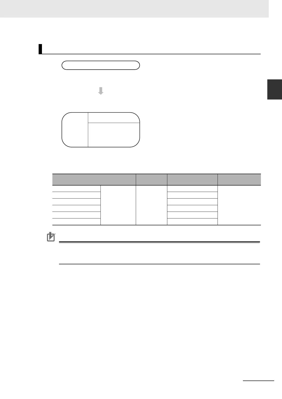
Flow of Operation
1
• Enable the required high-speed counters.
• Select the Use high speed counter Check Box for
high-speed counters 0 to 5. Set the input setting,
counting mode and reset method on the Built-in
Tab Page of the PLC Setup using the CX-Pro-
grammer.
• Terminals 00 to 06 on the 0CH terminal block can
be used for high-speed counters. High-speed
counters 0 to 5 correspond to terminals 00 to 05.
2
Write a program for interrupt tasks 0 to 15.
• Set the comparison values for the high-speed
counter and the interrupt tasks (0 to 15) to be
started using the CTBL instruction.
• Start the comparison using the INI instruction.
The comparison can be started simultaneously
when registering the comparison values using
the CTBL instruction.
Setting in PLC Setup
on Built-in Input Tab Page
Instruction CTBL port specifier (C1)
Interrupt task
number
High-speed counter 0 Select Use Check
Box.
CTBL #0000 0 to 15 (Specified by
user.)
High-speed counter 1 #0001
High-speed counter 2 #0002
High-speed counter 3 #0003
High-speed counter 4 #0004
High-speed counter 5 #0005
PLC Setup
Create
ladder
program
Interrupt task
Execution of CTBL and
INI instructions in a
cyclic task