12-47
12 Pulse Outputs
CP2E CPU Unit Software User’s Manual(W614)
12-9 Application Examples
12
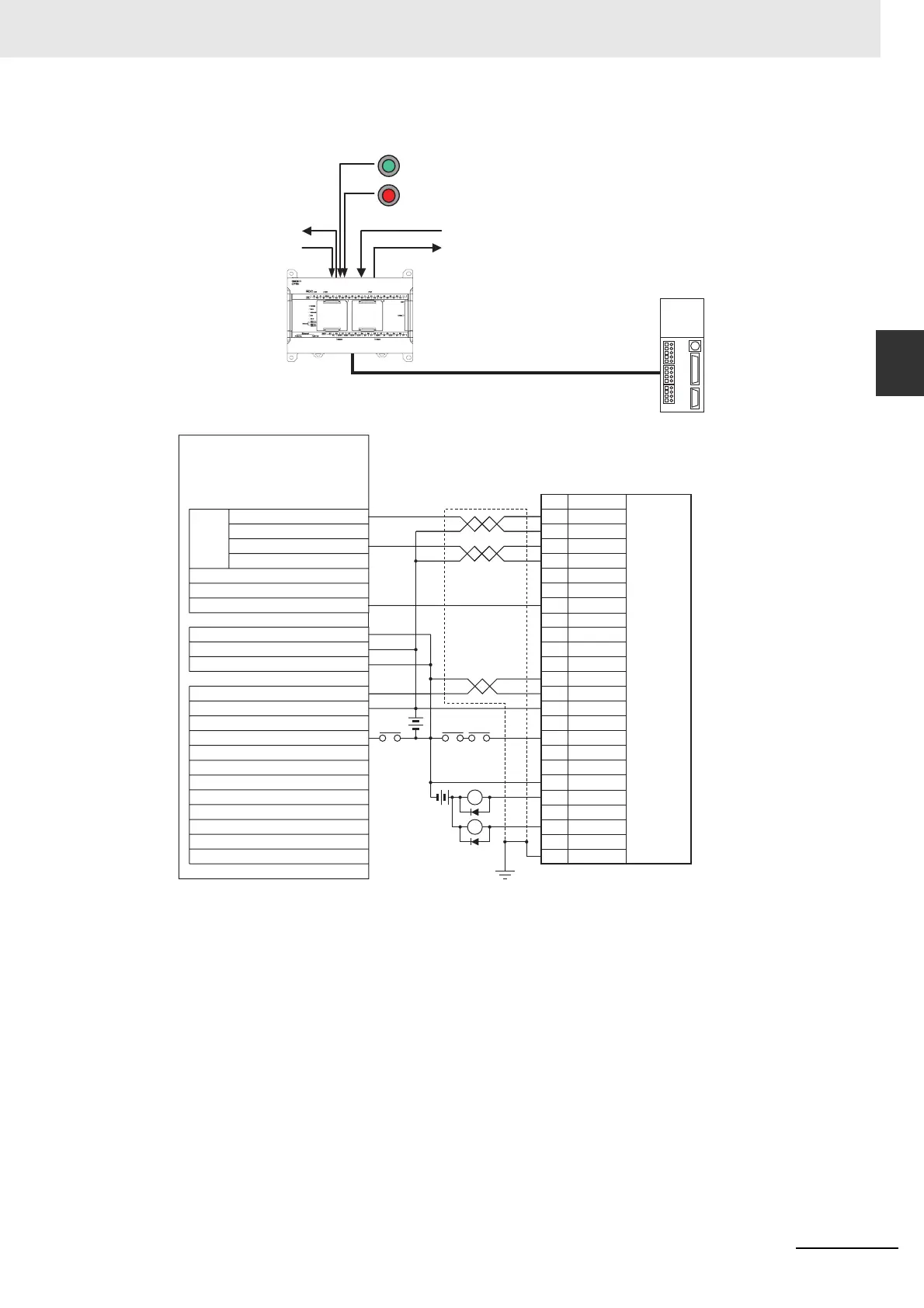
z Wiring Example Using G5-series Servo Drive
Only S-type CPU Units can wire V+ and V-. Do not wire them in N-type CPU Units.
z Operation
1
An origin search is performed using the Origin Search Start Switch (CIO 0.00).
2
When the origin search is finished, the PCB Storage Enabled Output (CIO 100.03) is turned ON.
3
When a PCB has been stored, the stocker is raised (relative positioning) using the PCB Storage
Completed Input (CIO 0.03).
4
Storing PCBs is repeated until the stocker is full.
5
The number of PCBs in the stocker is counted with counter C0 by counting the number of times
the stocker is raised.
6
When the stocker is full, it is moved (CIO 100.01) and only the conveyor is lowered (absolute
positioning) when stoker movement is completed (CIO 0.04).
7
An emergency stop is executed to stop pulse output with the Emergency Stop Switch Input (CIO 0.01).
Emergency Stop Switch (CIO 0.01)
PCB Storage Completed (CIO 0.03)
PCB Storage Enabled (CIO 100.03)
G5-series
Servo Drive
R88A-CPGS
Stocker Moved (CIO 100.01)
Stocker Movement Completed
(CIO 0.04)
Origin Search Start Switch (CIO 0.00)
Instruction pulse mode =
feed pulse and
forward/reverse signal
*
+24VCW
-PULS
ECRST
ZGND
+24VIN
Z
RUN
ALMCOM
BKIRCOM
/ALM
FG
X1
XB
24-VDC
X1
24-VDC
BKIR
+24VCCW
-SIGN
PIN
1
4
2
6
25
19
7
29
36
10
37
11
Hood
Output terminal block
CP2E N/S-type CPU Unit (Sinking outputs)
Pulse
output 0
Pulse output (CIO 100.00)
Direction output (CIO 100.02)
Error counter reset output 0 (CIO 100.04)
COM
V+ (S-type only)
V- (S-type only)
Input terminal block
Pulse 0 origin input signal (CIO 0.06)
COM
Pulse 0 origin proximity input signal (CIO 0.10)
G5-series
R88D-
KT
R88A-CPG
S
Signal
Servo Drive
RUN input