Appendices
A-66
CP2E CPU Unit Software User’s Manual(W614)
A274 10 High-speed Counter 0
Count Direction
This flag indicates whether the
high-speed counter 0 is currently being
incremented or decremented. The
counter PV for the current cycle is
compared with the PV in last cycle to
determine the direction.
ON: Incrementing
OFF: Decrementing
--- Cleared Setting used
for high-speed
counter, valid
during counter
operation.
A275 00 High-speed Counter 1
Range 1 Comparison
Condition Met Flag
These flags indicate whether the PV is
within the specified ranges when
high-speed counter 1 is being operated
in range-comparison mode for upper
and lower limits.
ON: PV in range
OFF: PV not in range
Cleared Cleared • Refreshed
each cycle
during the
overseeing
processes.
• Refreshed
when PRV
instruction is
executed to
read the
results of
range com-
parison.
• Refreshed
when range
comparison
table is reg-
istered.
01 High-speed Counter 1
Range 2 Comparison
Condition Met Flag
02 High-speed Counter 1
Range 3 Comparison
Condition Met Flag
03 High-speed Counter 1
Range 4 Comparison
Condition Met Flag
04 High-speed Counter 1
Range 5 Comparison
Condition Met Flag
05 High-speed Counter 1
Range 6 Comparison
Condition Met Flag
08 High-speed Counter 1
Comparison
In-progress Flag
This flag indicates whether a
comparison operation is being
executed for high-speed counter 1.
ON: Being executed
OFF: Stopped
--- Cleared Refreshed
when
comparison
operation
starts or stops.
09 High-speed Counter 1
Overflow/Underflow
Flag
This flag indicates when an overflow or
underflow has occurred in the
high-speed counter 1 PV. (Used with
the linear mode counting range only.)
ON: Overflow or
underflow
OFF: Normal
Cleared Cleared • Refreshed
when an
overflow or
underflow
occurs.
• Refreshed
when PV is
changed.
10 High-speed Counter 1
Count Direction
This flag indicates whether the
high-speed counter 1 is currently being
incremented or decremented. The
counter PV for the current cycle is
compared with the PV in last cycle to
determine the direction.
ON: Incrementing
OFF: Decrementing
--- Cleared Setting used
for high-speed
counter, valid
during counter
operation.
A276 --- Pulse
Output 0
PV
Lower four
digits
Contain the number of pulses output
from the corresponding pulse output
port.
PV range: 8000 0000 to 7FFF FFFF
hex
(-2,147,483,648 to 2,147,483,647)
When pulses are being output in the
CW direction, the PV is incremented by
1 for each pulse.
When pulses are being output in the
CCW direction, the PV is decremented
by 1 for each pulse.
PV after overflow: 7FFF FFFF hex
PV after underflow: 8000 0000 hex
Note If the coordinate system is rela-
tive coordinates (undefined ori-
gin), the PV will be cleared to 0
when a pulse output starts, i.e.
when a pulse output instruction
(SPED, ACC, PLS2, ITPL or
IFEED) is executed.
Cleared Cleared • Ref
reshed
each cycle
during the
overseeing
processes.
• Refreshed
when the INI
instruction is
executed
(PV
change).
A277 Upper four
digits
A278 --- Pulse
Output 1
PV
Lower four
digits
A279 Upper four
digits
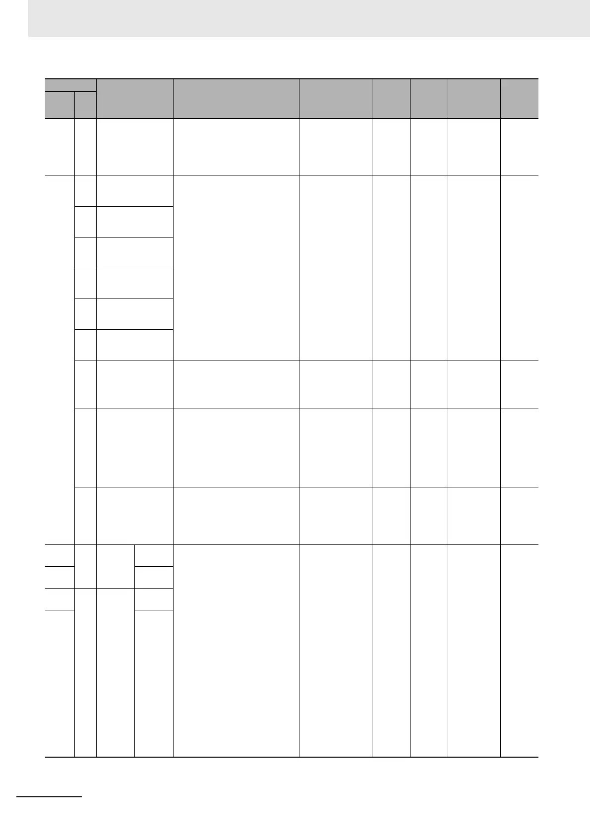
Address
Name Function Settings
Status
after
mode
change
Status at
startup
Write
timing
Related
flags,
settings
Words Bits