6-5SectionI/O Wiring
106
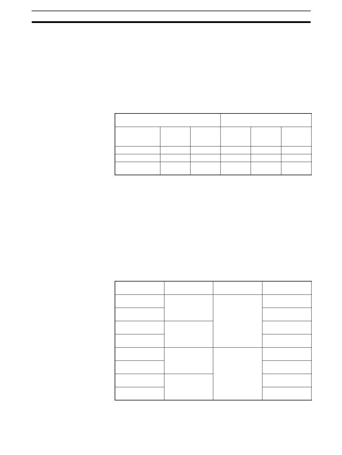
6-3-2 I/O Area Allocation
The Analog I/O Unit is allocated two input words in the CPU Unit for the two ana-
log inputs and one output word for the analog output. The following table shows
the allocations of the I/O area that are made depending on the model of CPU
Unit that is used.
For example, if an Analog I/O Unit is connected to a CPM1-10CDR- CPU Unit,
IR 001 and IR 002 in the CPU Unit will contain the decimal conversions of the
analog values input on analog input 1 and analog input 2, respectively, of the
Analog I/O Unit. Also, the analog conversion of the decimal value in IR 011 in the
CPU Unit will be output as a current and voltage on the analog output terminals
of the Analog I/O Unit.
CPU Unit CPM1A-MAD01
Analog I/O Unit
Model number Input
word
Output
word
Input
word for
input 1
Input
word for
input 2
Output
word
CPM1-10CDR-
IR 000 IR 010 IR 001 IR 002 IR 011
CPM1-20CDR-
IR 000 IR 010 IR 001 IR 002 IR 011
CPM1-30CDR-
IR 000
IR 001
IR 010
IR 011
IR 002 IR 003 IR 012
6-4 I/O Settings
The I/O ranges to be used by the Analog I/O Unit are set as range codes in the
output word allocated to the Unit. The range codes are shown in the following
table.
For example, if “FF04” is set as the range code, the ranges will be 0 to 10 V for
analog input 1, 1 to 5 V for analog input 2, and 0 to 10 V or 4 to 10 mA for the
analog output.
The I/O ranges must be set each time CPM1 operation is started. Analog and
digital conversions will not be conducted until the ranges are set.
The lower 8 bits of the analog output will be the analog conversion of 00 while the
range code is being set. Once the ranges have been set, they cannot be reset
without turning off the power to the CPM1. To change the range code, cycle the
power to the CPM1 and reset the code.
Range code Input 1 range Input 2 range Output range
(See note.)
FF00
0 to 10 V 0 to 10 V
0 to 10 V
4 to 20 mA
FF01 –10 to 10 V
4 to 20 mA
FF02
1 to 5 V or
4 to 20 mA
0 to 10 V
4 to 20 mA
FF03 –10 to 10 V
4 to 20 mA
FF04
0 to 10 V 1 to 5 V or
4 to 20 mA
0 to 10 V
4 to 20 mA
FF05 –10 to 10 V
4 to 20 mA
FF06
1 to 5 V or
4 to 20 mA
0 to 10 V
4 to 20 mA
FF07 –10 to 10 V
4 to 20 mA
Note The analog current output will always be output between 4 and 20 mA from the
I OUT terminal. (See 6-5-2 Output Wiring.) When using both the voltage and
current outputs, the total output current must be 21 mA or less.