6-5SectionI/O Wiring
107
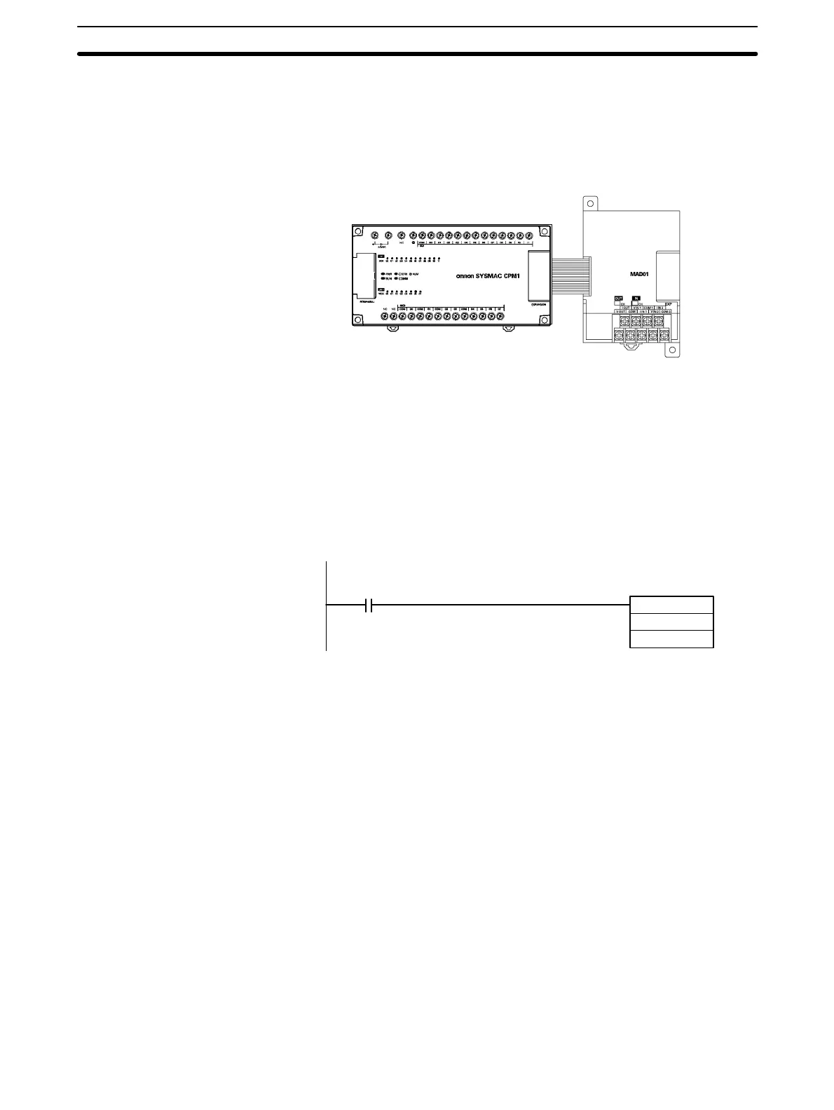
6-4-1 Setting Example
The following CPM1 PC consists of a 20-point CPU Unit and an Analog I/O Unit.
This example shows how to set this PC to input from 0 to 10 V and from 4 to
20 mA, and to output from 0 to 10 V.
CPM1-20CDR-
CPU Unit
CPM1A-MAD01
Analog I/O Unit
The I/O word allocations would be as follows:
• Analog input 1: IR 001
• Analog input 2: IR 002
• Analog output: IR 011
Here, the range code would be set to “FF04” to set analog input 1 to input from 0
to 10 V, analog input 2 to input from 4 to 20 mA, and the analog output to output
from 0 to 10 V.
The range code can be set by writing FF04 to IR 011 each time operation is
started. The following instructions can be used.
25315
MOV (20)
#FF04
011
(First Scan Flag)
Analog and digital conversions will be automatically started by the Analog I/O
Unit when the range code is set to any value between FF00 and FF07.