6-5SectionI/O Wiring
110
6-5 I/O Wiring
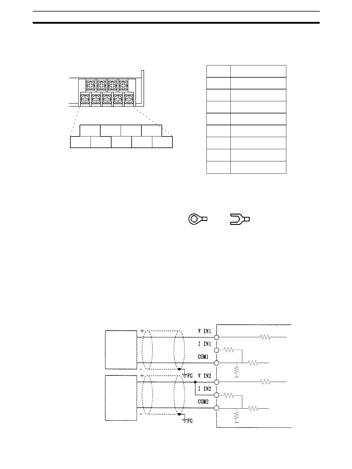
The I/O terminals are allocated as shown in the following illustration.
I OUT
V OUT
COM
V IN1
I IN1
COM1
V IN2
I IN2
COM2
Current output
Voltage output
Output common
Voltage input 1
Current input 1
Common for input 1
Voltage input 2
Current input 2
Common for input 2
I OUT
V OUT COM
V IN1
I IN1
COM1
V IN2
I IN2
COM2
I/O terminals
Note 1. Use crimp (solderless) terminals to connect to the I/O terminals on the Ana-
log I/O Unit. Do not connect loose wires.
2. The tightening torque of the I/O terminals is 0.5 Nm.
6-5-1 Input Wiring
Wire the analog inputs as shown in the following illustration. Use shielded
twisted-pair cables to connect field devices.
When using current inputs, always short the current and voltage input terminals.
Short the V IN, I IN, and COM terminals for all inputs that are not being used.
Voltage
output
device
Current
output
device
0 V
0 V
10 K
10 K
250 E
250 E
Analog I/O Unit
Shielded twisted-
pair cable