68
4-3-10 Checking the Program
This operation checks for programming errors and displays the program
address and error when errors are found. It is possible in PROGRAM mode
only.
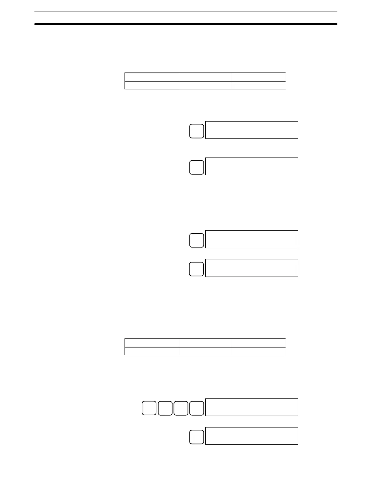
RUN MONITOR PROGRAM
No No OK
1, 2, 3... 1. Press the CLR Key to bring up the initial display.
2. Press the SRCH Key. An input prompt will appear requesting the desired
check level.
SRCH
00000PROG CHK
CHK LBL (0Ć2)?
3. Input the desired check level (0, 1, or 2). The program check will begin when
the check level is input, and the first error found will be displayed.
A
0
00178CIRCUIT ERR
OUT 00200
Note Refer to 5-5 Programming Errors for details on check levels.
4. Press the SRCH Key to continue the search. The next error will be dis-
played. Continue pressing the SRCH Key to continue the search.
The search will continue until an END instruction or the end of Program
Memory is reached. A display like this will appear if the end of Program
Memory is reached:
SRCH
00300NO END INST
END
A display like this will appear if an END instruction is reached:
SRCH
00310PROG CHK
END (001)00.3KW
If errors are displayed, edit the program to correct the errors and check the pro-
gram again. Continue checking the program until all errors have been corrected.
4-3-11 Bit, Digit, Word Monitor
This operation is used to monitor the status of up to 16 bits and words,
although only 3 can be shown on the display at any one time. Operation is
possible in any mode.
RUN MONITOR PROGRAM
OK OK OK
Program Read then Monitor When a program address is being displayed, the status of the bit or word in that
address can be monitored by pressing the MONTR Key.
1, 2, 3... 1. Press the CLR Key to bring up the initial display.
2. Input the desired program address and press the Down Arrow Key.
C
2
A
0
A
0
↓
00200READ
TIM 000
3. Press the MONTR Key to begin monitoring.
MONTR
T000
1234
If the status of a bit is being monitored, that bit’s status can be changed using
the Force Set/Reset operation. Refer to page 77 for details.
Programming Console Operations
Section 4-3