8
1-2 System Configuration
A CPM1 PC can consist of a single CPU Unit, a CPU Unit plus an Expansion I/O
Unit, or a CPU Unit plus an Analog I/O Unit. The CPU Units and Expansion I/O
Unit are described in this section. Refer to Section 6 Analog I/O Unit for details
on the Analog I/O Unit.
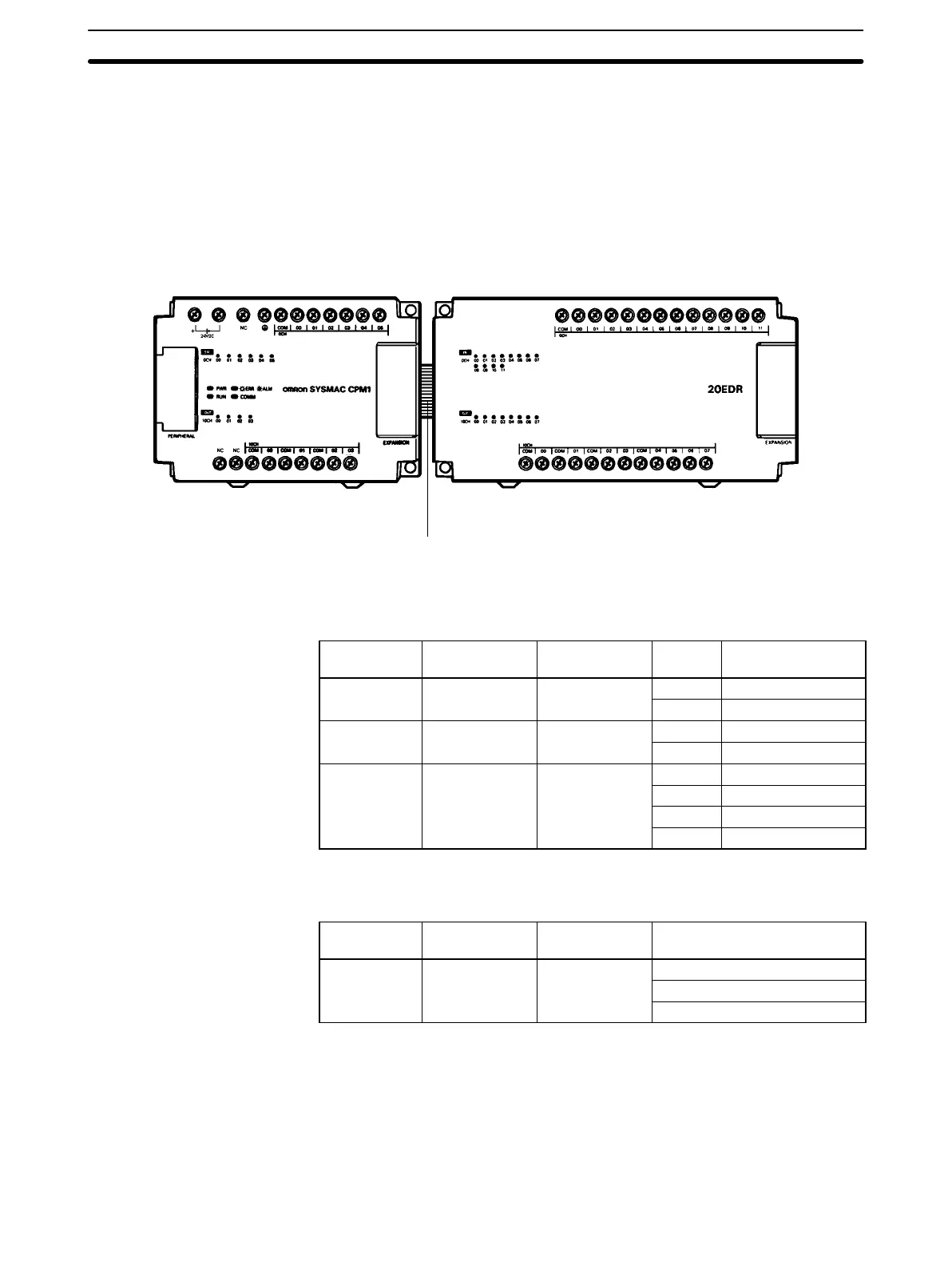
1-2-1 CPU Unit and Expansion I/O Unit Configuration
Expansion I/O Unit
Connecting Cable
CPM1 CPU Unit
CPM1 CPU Units The following table describes the six CPM1 CPU Units. All outputs are relay out-
puts.
Number of
I/O terminals
Inputs Outputs Power
supply
Model number
10 6 points 4 points
AC CPM1-10CDR-A
DC CPM1-10CDR-D
20 12 points 8 points
AC CPM1-20CDR-A
DC CPM1-20CDR-D
30 18 points 12 points
AC CPM1-30CDR-A
DC CPM1-30CDR-D
AC CPM1-30CDR-A-V1
DC CPM1-30CDR-D-V1
CPM1 Expansion I/O Unit The following table describes the CPM1 Expansion I/O Unit. All outputs are relay
outputs.
Number of
I/O terminals
Inputs Outputs Model number
20 12 points 8 points
CPM1-20EDR
CPM1A-20EDT
CPM1A-20EDT1
• CPM1 Expansion I/O Units can also be connected to CPM1A Expansion I/O
Units with transistor output.
• Either one Expansion I/O Unit or one Analog I/O Unit can be connected to a
CPM1-10CDR-/20CDR-/30CDR- CPU Unit. Also, up to three Expan-
sion I/O Units and/or Analog I/O Units can be connected in any combination to
a CPM1-30CDR--V1 CPU Unit. (Refer to Section 6 Analog I/O Unit for
details on the Analog I/O Unit.
System Configuration
Section 1-2