6-5SectionI/O Wiring
108
6-4-2 Analog Inputs and Conversion Results
When the range code is set in the output word, the analog inputs are automati-
cally converted to digital values and stored in the input words allocated to them.
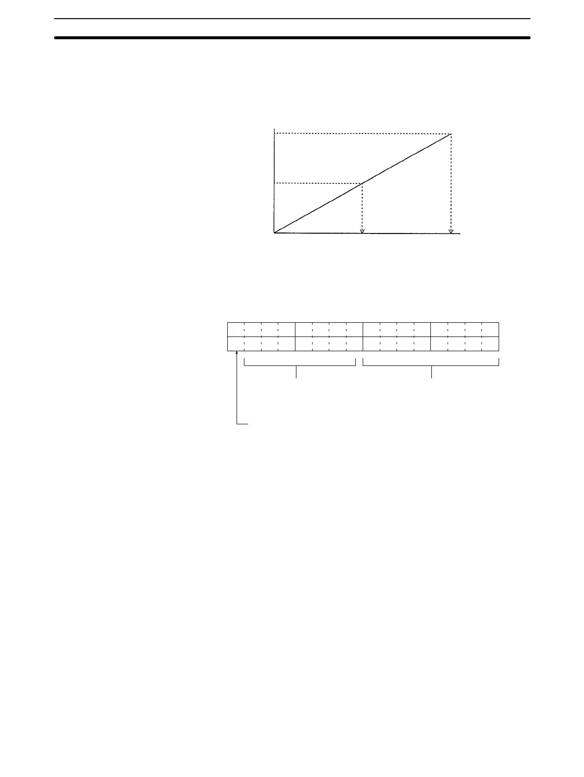
The values are converted as shown in the following chart.
Analog input
10 V 5 V 20 mA
5 V 3 V 12 mA
0 V 1 V 4 mA
00 80 FF
Converted data
(Hexadecimal)
In the example shown in 6-4-1 Setting Example, analog input 1 is allocated IR
001 and analog input 2 is allocated IR 002. The results of digital conversion for
these inputs would be stored in these words in the following form.
15 14 13 12 11 10 09 08 07 06 05 04 03 02 01 00
Not used (00) Results of conversion
(00 to FF)
Broken Wire Bit
0: No broken wire
1: Broken wire
Note The Broken Wire Bit will turn ON when the voltage drops below 1 V for a 1 to 5-V
input signal or below 4 mA for a 4 to 20-mA input signal.
Analog Input vs.
Conversion Results
Input Word Results Data