6-5SectionI/O Wiring
109
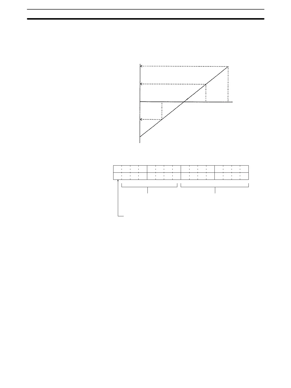
6-4-3 Analog Output Data and Output Value
When the range code is set in the output word, the output data in the output word
is converted to an analog signal that is output as a voltage and current. The data
is converted as shown in the following chart.
10 V 5 V 20 mA
5 V 3 V 12 mA
0 V 1 V 4 mA
80FF 8080
0000
0080 00FF
–5 V
–10 V
Output data
(Hexadecimal)
Analog output
In the example shown in 6-4-1 Setting Example, the analog output is allocated IR
011. The output word data is thus stored in IR 011, in the following form.
15 14 13 12 11 10 09 08 07 06 05 04 03 02 01 00
Not used (ignored) Output data
(00 to FF)
Sign Bit
0: Positive
1: Negative (See note.)
Note The Sign Bit is valid only when the range is set to –10 to 10 V. The Sign Bit is
ignored when the range is set to 0 to 10 V.
Output Data vs. Output
Value
Output Word Data