43
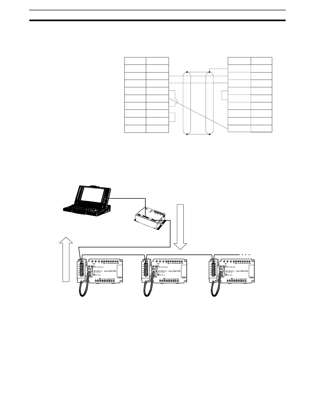
The following diagram shows the wiring in the RS-232C cable used to connect a
CPM1 to a host computer or Programmable Terminal.
IBM PC/AT compatible computer
or Programmable Terminal (9-pin)
RS-232C Adapter
1
2
3
4
5
6
CD
RD
SD
ER
SG
DR
RS
CS
CI
7
8
9
1/Cover
2
3
4
5
6
7
8
9
FG
SD
RD
RS
CS
–
–
SG9
Pin No.Signal
–
Pin No. Signal
Note When the CPM1 is connected to a host computer, set the RS-232C Adapter’s
mode setting switch to “HOST.”
1:n Host Link Connection Up to 32 CPU Units (CPM1 only) can be connected to an IBM PC/AT compatible
computer or a Programmable Terminal with a B500-AL004 Link Adapter and
RS-422 Adapters, as shown in the following diagram.
CPM1
CPU Unit
RS-422
Adapter
CPM1
CPU Unit
RS-422
Adapter
CPM1
CPU Unit
RS-422
Adapter
Response
Command
Link Adapter
3G2A9-AL004-E
Wiring and Connections
Section 3-4