51
RFID System
Operation Manual
Section 3 Switch Settings
Section 3
Preparing Communications
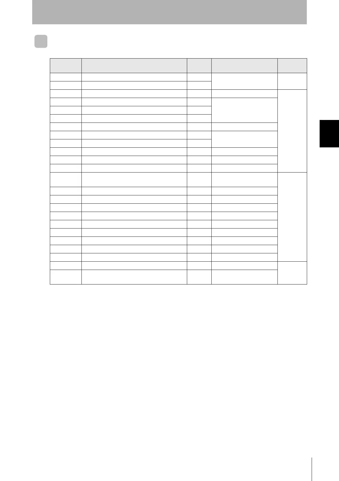
Factory Settings
Name
Factory
setting
Description
More
information
SW1 Controller Number Switch 1 (Upper digit: 0 to 9) 0 Controller number 00
p.52
SW2 Controller Number Switch 2 (Lower digit: 0 to 9) 0
SW3 pin 1 DIP switch/internal setting selector OFF DIP switches enabled
p.53
SW3 pin 2 Baud rate setting 1 OFF Baud rate: 2,400 bps
SW3 pin 3 Baud rate setting 2 OFF
SW3 pin 4 Baud rate setting 3 OFF
SW3 pin 5 Data length setting OFF Data length: 7 bits
SW3 pin 6 Parity setting 1 OFF Parity: Even
SW3 pin 7 Parity setting 2 OFF
SW3 pin 8 Stop bit setting OFF Stop bits: 2 bits
SW3 pin 9 Communications protocol setting OFF 1:1
SW3 pin 10 Reserved. OFF Not used.
SW4 pin 1
Priority mode switch
OFF
Communications distance
priority
p.54
SW4 pin 2 Verify setting OFF Verification enabled
SW4 pin 3 Display switch OFF End code display
SW4 pin 4 Lower trigger execution OFF No lower trigger
SW4 pin 5 Reserved. OFF Not used.
SW4 pin 6 Test switch OFF Test stopped
SW4 pin 7 Reserved. OFF Not used.
SW4 pin 8 TEST head specification OFF Read/Write Head 1 designated
SW4 pin 9 TEST command specification OFF Read test
SW4 pin 10 Reserved. OFF Not used.
SW5 Mode switch OFF RUN mode
p.55
SW6
Terminating resistance switch
OFF
Terminating resistance not
connected.

 Loading...


