6-21
6
Switching Over the Acceleration and Deceleration Time Using Multi-Function Input
Commands
When two digital input terminals are set to “Accel./Decel. time switch over 1 and 2” (H1-=7 and 1A), the
acceleration/deceleration times can be switched over even during operation by a binary combination of the
inputs. The following table shows the acceleration/deceleration time switching combinations.
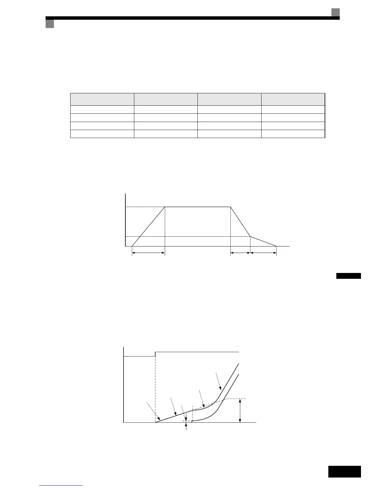
Automatic Deceleration Time Switch Over Using a Speed Level
The deceleration times C1-02 and C1-08 can be switched over automatically at a certain speed which can be
set in parameter C1-11. Fig 6.4 shows the working principle of the function.
Set C1-11 to a value other than 0.0 Hz. If C1-11 is set to 0.0 Hz, the function will be disabled.
Fig 6.4 Acceleration/deceleration Time Switching Frequency
Dwell at Start Function (Closed Loop Vector only)
The Dwell function can be used to reduce a staring jerk caused by high static friction.
After a start command, the output frequency is increased up to the Dwell speed set in parameter S1-26 using
the acceleration time C1-07. As soon as the motor starts turning and the motor speed (PG feedback) reaches
the acceleration time switching level C1-11, the acceleration is continued using the selected acceleration time
starting with the S-curve set in parameter C2-01.
Fig 6.5 Dwell at start function
Note: When C1-11 is set much higher than S1-26, the motor speed cannot reach C1-11 and the motor can not accelerate to the selected speed. Therefore
always set C1-11 equal or lower than S1-26!
Acceleration/Deceleration
Time Selection 1 Terminal
Acceleration/Deceleration
Time Selection 2 Terminal
Acceleration Time Deceleration Time
OFF OFF C1-01 C1-02
ON OFF C1-03 C1-04
OFF ON C1-05 C1-06
ON ON C1-07 C1-08
Output
Frequency
Decel. time
Switching Freq.
C1-11
C1-01 C1-02 C1-08
When output frequency ≥ C1-11the deceleration time 1 (C1-02) is used.
When output frequency < C1-11the deceleration time 4 (C1-08) is used.
No S-Curve
C1-07
C1-11
C2-01
C1-02
RUN
S1-26