6-56
6
Output Terminal Functions
The digital multifunction outputs can be set to several functions using the H2-01 to H2-03 parameters (termi-
nal M1 to M6 function selection). These functions are described in the following section.
Related Parameters
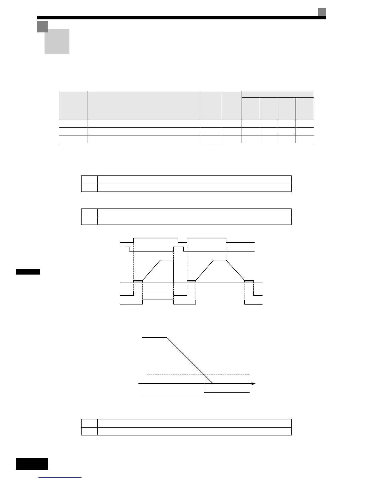
During Run (Setting: 0) and During Run 2 (Setting: 37)
During Run (Setting: 0)
During Run 2 (Setting: 37)
These outputs can be used to indicate the inverter’s operating status.
Fig 6.22 Timing Chart for “During RUN” Output
Zero Speed (Setting: 1)
Fig 6.23 Timing Chart for Zero-speed
* The Zero Speed Level depends on the control mode. It is 0.1 Hz for Closed Loop Vector, 0.5 Hz for Open Loop Vector and 1.2 Hz for V/f control.
Parameter
No.
Name
Factory
Setting
Change
during
Opera-
tion
Control Methods
V/f
Open
Loop
Vector
Closed
Loop
Vector
Closed
Loop
Vector
(PM)
H2-01Terminal M1-M2 function selection 0 NoAAAA
H2-02Terminal M3-M4 function selection 1 NoAAAA
H2-03Terminal M5-M6 function selection 2 NoAAAA
OFF The Run command is OFF and there is not output voltage.
ON The Run command is ON or a voltage is being output.
OFF The inverter is not outputting a frequency. (Baseblock, DC injection braking or stopped)
ON The inverter is outputting a frequency.
OFF The output frequency is higher than the zero speed level*.
ON The output frequency is lower than the zero speed level*.
Run
Baseblock
Output frequency
During Run 1 Output
During Run 2 Output
OFF
ON
DC Inj DC Inj
OFF
ON
OFF
ON
OFF
ON
Zero Speed Level*
Zero Speed
Output
Output
Frequency
OFF
ON