6-64
6
Digital Operator/LED Monitor Functions
Setting Digital Operator/LED Monitor Functions
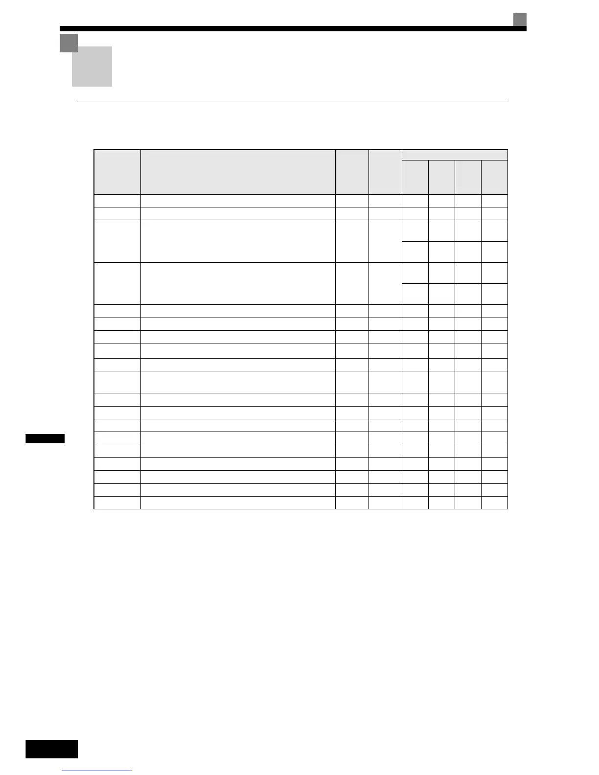
Related Parameters
Monitor Selection (o1-01)
Using parameter o1-01 the third monitor item that is displayed in drive mode can be selected. This function
has no effect on the LCD-operator (JVOP-160-OY).
Monitor Display when the Power Supply is Turned ON (o1-02)
The parameter o1-02 selects the monitor item (U1-), which is to be displayed in the first line on the Digi-
tal Operator when the power supply is turned ON.
Changing Frequency Reference and Display Units (o1-03)
Parameter o1-03 sets the display units of some frequency/speed related parameters on the Digital Operator.
The setting in o1-03 affects the display units of the following monitor items:
• U1-01 (Frequency Reference)
• U1-02 (Output Frequency)
• U1-05 (Motor Speed)
Parameter
No.
Name
Factory
Setting
Change
during
Opera-
tion
Control Methods
V/f
Open
Loop
Vector
Close
d Loop
Vector
Closed
Loop
Vector
(PM)
o1-01 Monitor selection 6 Yes A A A A
o1-02 Monitor selection after power up 1 Yes A A A A
o1-03 Frequency units of reference setting and monitor
i
No
A
0
A
0
A
0
-
---
A
1
o1-04 Setting unit for frequency reference related parameters
i
No
--
A
0
-
---
A
1
o1-05 LCD Display contrast 3 Yes A A A A
o2-02 STOP key during control circuit terminal operation 0 No A A A A
o2-03 User parameter initial value 0 No A A A A
o2-04 Inverter kVA selection
0
*1
*1. Depends on the inverter capacity
No AAAA
o2-05 Frequency reference setting method selection 0 No A A A A
o2-06
Operation selection when digital operator/LED Monitor is dis-
connected
0 No AAAA
o2-07 Cumulative operation time setting 0 No A A A A
o2-08 Cumulative operation time selection 0 No A A A A
o2-09 Initialize Mode 2 No A A A A
o2-10 Fan operation time setting 0 No A A A A
o2-12 Fault trace initialize 0 No A A A A
o2-15 “Number of Travels” monitor initialize 0 No A A A A
S3-13 Traction sheave diameter 400 mm No A A A A
S3-14 Roping ratio 2 No A A A A
S3-15 Gear ratio 1.000 No A A A A